Installation Note N9030-90058 15
Option EXM, External Mixing Upgrade Kit
Add Cables to A13 Front End and A15 Front End Controller, Millimeter Wave
PXAs
NOTE This procedure only applies to millimeter wave PXAs (frequency range options
543, 544, and 550). If your PXA has frequency range option 503, 508, 513, or 526,
refer to the “Add Cables to A13 Front End and A15 Front End Controller,
RF/Microwave PXAs” earlier in this note.
1. Locate the shorter of the two flexible coax assemblies in the Opt EXM Cable Kit with Markers.
This is cable W30 and should be labeled “8120-2025” and have the ends labeled “903” and “13”
2. Connect the end of W30 that is labeled “903” to A15J903.
3. Connect the end of W30 that is labeled “13” to A13A1J13. J13 is one of the connectors along the
top side of A13. Torque the cable nut to 10 inch-pounds.
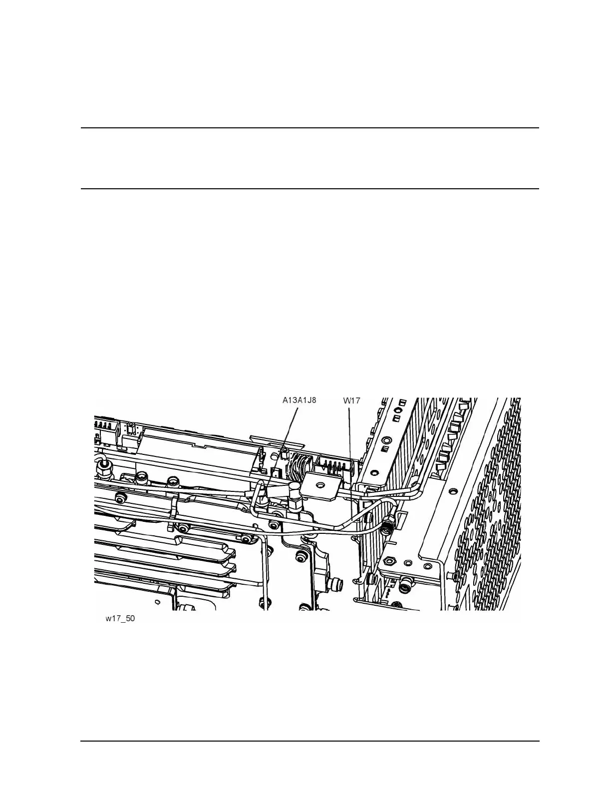
4. Remove the SMA termination on A13A1J8. A13A1J8 is to the left of A13A1J13.
5. Locate semi-rigid coax cable, part number N9020-20167, in the upgrade kit. This is W17. Connect
the end with the SMA male connector A13A1J8, with the SMA female connector pointing towards
where the front panel would be. The long, straight section of W17 should be parallel to the casting
of the A13 Front End and level. Refer to Figure 8. Note that W29 is routed below W17. Torque the
cable nut to 10 inch-pounds.
Figure 7 Orientation of W17 in a Millimeter Wave PXA

 Loading...