3
KMC100
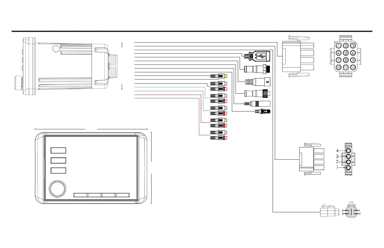
Installation Overview
3” Hole Cutout
1- Red, Switched 12V+
2- White/Blk, Left Front Spkr, Negative
3- White, Left Front Spkr, Positive
4- Orange, Dimmer
5- Grey/Blk, Right Front Spkr, Negative
6- Grey, Right Front Spkr, Positive
7- Blue/Wht, Amp Turn-on
8- Green/Blk, Left Rear Spkr, Negative
9- Green, Left Rear Spkr, Positive
10- Black, Ground
11- Purple/Blk, Right Rear Spkr, Negative
12- Purple, Right Rear Spkr, Positive
1- RGB Black +12v
2- RGB Red GND
3- RGB Green GND
4- RGB Blue GND
1- Zone 2 Brown/Blk, Right Negative
2- Zone 2 Brown, Right Positive
3- Zone 2 Pink/Blk, Left Negative
4- Zone 2 Pink, Left Positive
1
2
3
4
5
6
7
8
9
10
11
12
13
14
15
16
1. Main Harness
2. Zone 2 Harness
3. RGB Input Harness
4. USB Port
5. NMEA Port
6. SiriusXM Port
7. Digital Remote Port
8. Antenna Input
9. Remote Port
10. Video RCA Input
11. Reverse Trigger Wire
12. AUX Input
13. Front RCA Output
14. Rear RCA Output
15. Subwoofer RCA Output
16. Zone 2 RCA Output
5.5”
3.5”