3-1290-FM200M-000 September 2004
FM-200
®
ECS Series Engineered Fire Suppression Systems
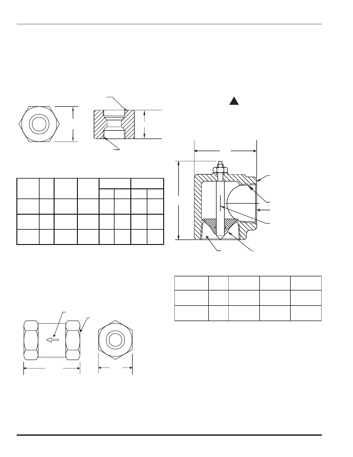
3-3.7.2 VALVE OUTLET ADAPTERS,
P/N 283904, P/N 283905 AND P/N 283906
A valve outlet adapter connects the cylinder valve outlet to
the discharge piping when a flexible discharge hose is not
used (see Figure 3-25 and Table 3-14).
Note: 3" valve cylinders are equipped with a roll-groove
outlet. Use a standard groove-groove connection
in lieu of a valve outlet adapter.
C
D
A (system pipe connection)
B (valve outlet connection)
Figure 3-25. Valve Outlet Adapter
Table 3-14. Dimensions, Valve Outlet Adapter
Part
Number
Size A B
CD
in. mm in. mm
283904 1½"
1½" to
11½ NPT
1.874" 2.69 68.33
2.50
HEX
63.50
283905 2"
2" to
11½ NPT
2.500"
12 UNJ
3.12 79.25
3.00
HEX
76.20
283906 2½"
2½"to
8 NPT
3.00"
12 UNJ
3.00 76.20
3.75
HEX
96.25
3-3.7.3 CHECK VALVE, 1/4-INCH, P/N 264985
Check Valves are installed in sections of piping in main/
reserve systems to prevent the actuation of the reserve
system when the main system is discharged.
1/4-inch check valves are installed in the pilot manifold to
ensure the proper number of cylinders are discharged (see
Figure 3-26).
DIRECTION
OF FLOW
1/4"-18NPT (TYP.)
2.00"
(51 mm)
Note: Install the valve with the arrow pointing in the direction of flow.
0.81"
HEX
(21 mm)
Figure 3-26. Check Valve
3-3.7.4 MANIFOLD EL-CHECKS, P/N 877690 AND
P/N 878743
Manifold El-Checks are installed at the discharge manifold
in a multiple cylinder arrangement to allow removal of any
FM-200 cylinder from the manifold while still retaining a
closed system. The 2-inch El-check is used on the
10 through 350 lb. size cylinders; the 2½-inch El-check is
used with the 600 lb. size cylinder (see Figure 3-27 and
Tables 3-15 and 3-16).
CAUTION
!
Manifold El-checks are not intended to be
used as check valves in main/reserve
systems. Improper use of equipment can
cause system malfunction.
A
B
VALVE BODY
C
C
CHECK
FOR CONNECTION
TO SYSTEM
ARROW
INDICATES FLOW
Figure 3-27. Manifold El-Checks
Table 3-15. Dimensions, Manifold El-Checks
rebmuNtraPeziSA B C
096778"2
"39.3
)mm8.99(
"88.4
)mm59.321(
TPN½11"2
347878"½2
"69.4
)mm911(
"67.5
)mm3.641(
TPN8"½2
 Loading...