3-13September 2004 90-FM200M-000
FM-200
®
ECS Series Engineered Fire Suppression Systems
Table 3-16. Check Valves, Equivalent Lengths
Part Number Nomenclature Pipe Type
Equivalent
Length
ft. m
800327
Check Valve,
1/2" NPT
40 T & 40 W 7.0 2.13
800266
Check Valve,
3/4" NPT
40 T & 40 W 17.0 5.18
800443
Check Valve,
1" NPT
40 T & 40 W 12.0 3.66
800444
Check Valve,
1¼" NPT
40 T & 40 W 51.0 15.54
870152
Check Valve,
1½" NPT
40 T & 40 W 57.0 17.37
870151
Check Valve,
2" NPT
40 T & 40 W 165.0 50.29
870100
Check Valve,
3" NPT
40 T & 40 W 795.0 242.31
06-118213-001
Swing Check,
2"
40T & 40 W 13.4 4.06
06-118058-001
Swing Check,
3"
40 T & 40 W 13.0 3.96
877690 and
283899
2" EI check
and Flex Hose
40 T & 40 W 16.0 4.88
878743 and
283900
2½" EI check
and Flex Hose
40 T & 40 W 17.5 5.33
3-3.7.5 PRESSURE OPERATED SWITCHES,
P/N 486536 AND P/N 981332
Pressure Switches operate from system pressure upon dis-
charge to energize or de-energize electrically operated
equipment. Pressure switches may be used to shut down
machinery and ventilation or to annunciate system dis-
charge (see Figures 3-31 and 3-32).
3-3.7.6 PRESSURE OPERATED TRIP,
P/N 874290
Pressure Operated Trips are used to close off the hazard
space upon system discharge. The trips, operated by sys-
tem pressure, are designed to release self-closing units for
doors, windows and dampers. The maximum load to be
attached to a pressure trip is 100 lb. (45.36 kg). This is
based on a minimum pressure of 75 PSIG (50.7 bar gauge)
at the pressure trip.
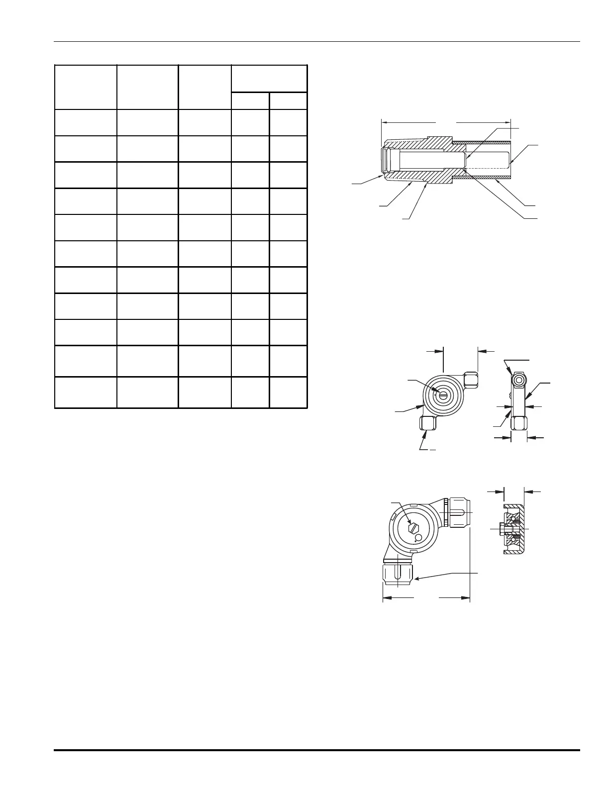
3-3.7.7 DISCHARGE INDICATOR, P/N 875553
The Discharge Indicator may be installed in the discharge
piping to visually indicate a system discharge. When in the
SET position, the discharge indicator acts as a vent (see
Figure 3-28).
2.62"
(67 mm)
BODY
NPT MALE
0.93"(24 mm) HEX
ACROSS FLATS
½”
POSITION
INDICATION
POSITION
DISCHARGE
NORMAL
STEM-RED
CAP
Figure 3-28. Discharge Indicator
3-3.7.8 CORNER PULLEYS, P/N 803808
AND P/N 844648
Corner Pulleys change the direction of cable lines without
binding to ensure smooth operation. P/N 803808 is used
for all watertight applications; P/N 844648 is used for all
industrial applications (see Figures 3-29 and 3-30).
GASKET
BODY
COVER
0.62"
(16 mm)
0.81"
(21 mm)
1.75"
(45 mm)
COVER SCREW
2.13" (54 mm) DIA
-18 NPS FEMALE
3"
8
Figure 3-29. Corner Pulleys, Watertight Applications
U
L
COVER SCREW
2 - ½” E.M.T. CONNECTIONS
COMPRESSION TYPE
0.62"
(16 mm)
2.75"
(70 mm)
approx.
Figure 3-30. 1/2-Inch E.M.T. Corner Pulley,
General Applications
 Loading...