6-1September 2004 90-FM200M-000
FM-200
®
ECS Series Engineered Fire Suppression Systems
CHAPTER 6
POST-DISCHARGE MAINTENANCE
6-1 INTRODUCTION
Follow these procedures after the system has been acti-
vated and FM-200
®
has been discharged.
6-2 POST FIRE MAINTENANCE
6-2.1 FM-200 Valve Inspection and Service
Inspect and service the FM-200 valve as follows:
Note: ImportantBecause FM-200 tends to dissolve and
wash out lubricant, certain components in the
FM-200 valve assembly will have to be inspected
and serviced before recharging the cylinder/valve
assembly. Part numbers for items which may re-
quire replacement are listed in Table 6-1.
6-2.2 Valve Disassembly (1½", 2" and 2½")
Refer to Figures 6-1 and 6-2 and Table 6-1.
WARNING
!
Before removing the valve, make sure that all
pressure has been relieved from the cylinder.
To relieve any remaining pressure, depress the
pressure switch Schraeder valve until all
pressure is relieved.
1. Remove the valve with the siphon tube from the cylinder.
2. Remove the O-ring. Examine the O-ring for cuts or nicks
and replace if necessary. Before reinstalling the O-ring,
apply a lubricant.
3. Remove the valve cap, spring and piston assembly.
Note: All internal components of FM-200 valves are re-
moved from the top of the assembly. However, if
there is excessive piston O-ring friction, the siphon
tube may have to be removed and the piston as-
sembly pressed out from the bottom.
4. Remove the O-rings and examine for cuts or nicks;
replace if necessary. Examine the O-ring grooves for
foreign matter. Before reinstalling the O-rings, apply
a lubricant.
5. Examine the exposed surface of the O-ring for nicks
and cuts. Also, ensure that the O-ring protrudes a mini-
mum or 0.020 in. (0.5 mm) above the conical seating
surface of the piston assembly. Replace this O-ring if
necessary by removing the seat retainer. Before reas-
sembly, apply a lubricant to the O-ring.
6. Examine the valve core pin for any evidence of bend-
ing or other damage. Depress the pin and make cer-
tain it snaps back freely. Replace the valve core if
necessary using a standard Schraeder core wrench.
When reinstalling a new Schraeder core element,
torque to 1½ to 3 in. lb. (0.17 to .37 N-m).
CAUTION
!
After reinstalling a Schraeder core, the distance
from the top of the core pin to the control head
seating surface must fall between the
dimensions of 0.515 in. to 0.565 in. (13 mm to
14 mm) when in the shut or non-actuated
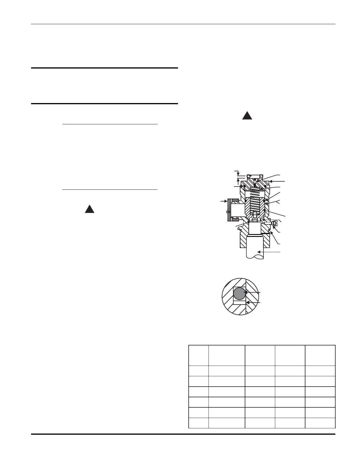
position (see Figure 6-1).
SPRING
VALVE CAP
VALVE CORE
BACK-UP RING
O-RING, PISTON,
BACK-UP RING
(See enlarged view
in Figure 6-2.)
PISTON
O-RING SEAT
¬
¯
SIPHON TUBE
SAFETY
CAP
GAGING DIMENSIONS
.515/.565
O-RING CAP
SEAT RETAINER
O-RING, NECK
SUPERVISORY PRESSURE
SWITCH CONNECTION
°
±
®
Figure 6-1. Valve Assembly (1½", 2" and 2½")
O-RING, PISTON
TEFLON BACK-UP
RING
Figure 6-2. Piston O-Ring
Table 6-1. Valve Components
erugiF
metI
.oN
noitpircseD
.bl521-01
srednilyc
.bl053-002
srednilyc
.bl006
srednilyc
1pac,gnir-O5220-16650320-166
54320-1665
2notsip,gnir-O5230-16650330-16654330-1665
3taes,gnir-O5120-16656230-16651330-1665
4kcen,gnir-O2390-166553
30-16659330-1665
5erocredearhcS872022872022872022
6gnirpu-kcaB052-300455003-300455043-300455
 Loading...