6-290-FM200M-000 September 2004
FM-200
®
ECS Series Engineered Fire Suppression Systems
Table 6-2. Other Valve Component Materials
slairetaMrehtOerutalcnemoNdnarerutcafunaM
tnacirbuLtnelaviuqeroebuL-O-repuS.oClaeSrekraP
tnalaeSetitcoLtne
laviuqeroVCedarG,tnalaeS.proCetitcoL
remirPciuqcoLtnelaviuqeroNedarG,remirP.proCetitcoL
6-2.3 Valve Disassembly (3")
Note: Refer to Figure 6-3 for items.
1. Remove the valve with the siphon tube from the cylinder.
2. Remove the O-ring and examine it for cuts and nicks;
replace if necessary. Before reinstalling the O-ring, ap-
ply lubricant.
3. Remove the valve cap, spring and piston assembly.
Note: Remove all internal components of the FM-200
valve from the top of the assembly. However, if
there is excessive piston O-ring friction, the siphon
tube may have to be removed and the piston as-
sembly pressed out from the bottom.
4. Remove the O-rings and examine them for cuts and
nicks; replace if necessary. Examine the O-ring
grooves for foreign matter. Before reinstalling the
O-rings, apply lubricant.
5. Examine the exposed surface of O-ring for nicks and
cuts. Also, ensure that the O-ring protrudes a minimum
of 0.020 in. (0.5 mm) above the conical seating sur-
face of the piston assembly. Replace this O-ring if nec-
essary by removing the seat retainer. Before
reassembling, apply lubricant to the O-ring.
6. Examine the pilot check for any evidence of bending or
other damage. Depress the check and make certain it
snaps back freely. Replace pilot check if necessary.
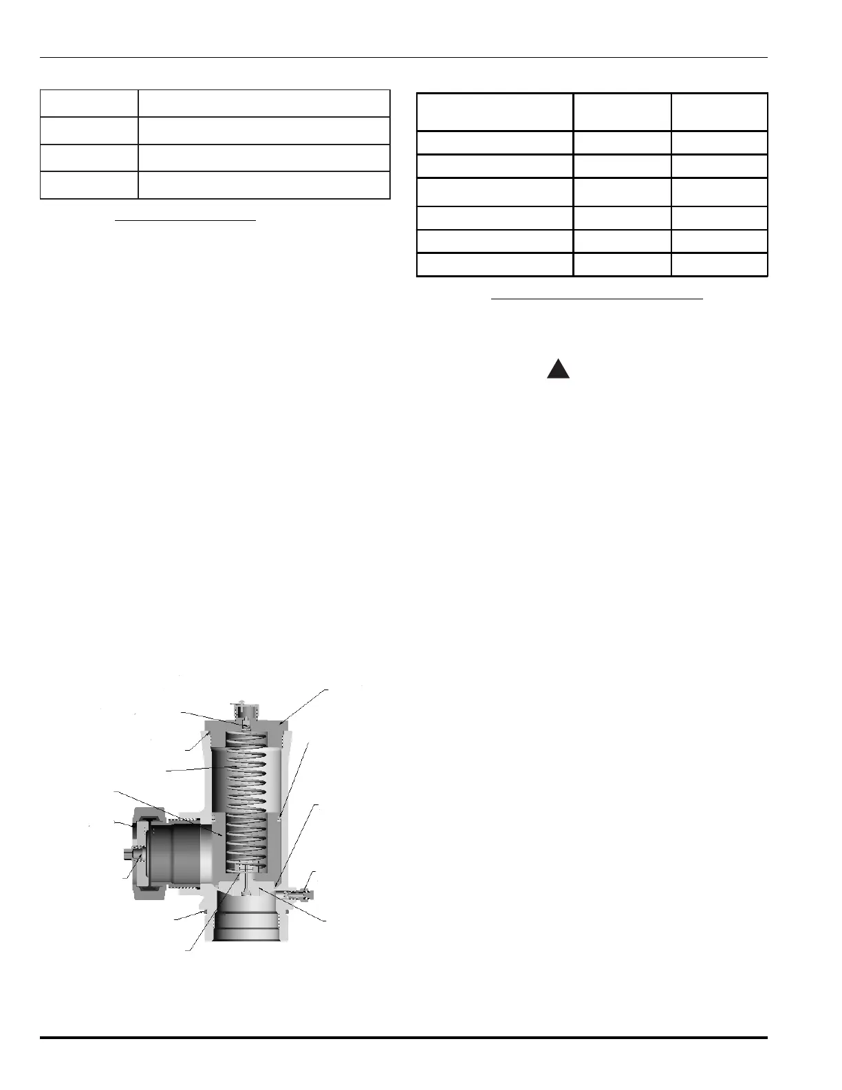
Valve Cap
Piston O-Ring
WK-566103-370
Back-Up Teflon Ring
WK-554003-400
Retainer O-Ring
WK-566103-400
Supervisory Pressure
Switch Connection
Retainer
06-235924-001
Inner Piston O-Ring
WK-566101-170
Neck O-Ring
WK-566103-470
Refill Part
(½ inch NPT Thread)
Safety Cap
Piston
Spring
Valve Cap O-Ring
WK-566102-410
Pilot Check
WK-923066-000
Pilot Check Spring
WF-230640-000
Figure 6-3. 3" Valve Assembly
Table 6-3. 3" Valve Components
Description
600 lb.
Cylinders
900 lb.
Cylinders
O-ring, Cap 566102410 566102410
O-ring, Piston 566103370 566103370
O-ring, seat 566103400 566103400
O-ring, Neck 566103470 566103470
Pilot Check Assembly 923066 923066
Back-up Ring 554003400 554003400
6-2.4 Valve Assembly (1½", 2", and 2½")
Note: The items refer to Figure 6-1.
1. Install an O-ring in the piston groove.
CAUTION
!
Make certain the Teflon
®
back-up ring is below
this O-ring as shown in Figure 6-2.
2. Press the piston (Item 6) back into the valve body.
3. Install the spring.
4. Install the O-ring (Item 1) onto the groove in the valve
cap, screw the cap into the valve body and torque to
250 in. lb. (28.2 N-m).
5. If the siphon tube had to be removed to disassemble
the valve, wire brush the siphon tube threads to re-
move the old Loctite
®
residue.
6. Apply a film of Loctite
®
primer to the siphon tube threads
and allow three to five minutes to dry.
7. Apply a film of Loctite
®
sealant to the threads and rein-
stall the siphon tube.
8. Install the O-ring onto the valve neck groove, screw
the valve and siphon tube into the cylinder, and torque
to 50 to 55 ft. lb. (68 to 75 N-m).
 Loading...