6-490-FM200M-000 September 2004
FM-200
®
ECS Series Engineered Fire Suppression Systems
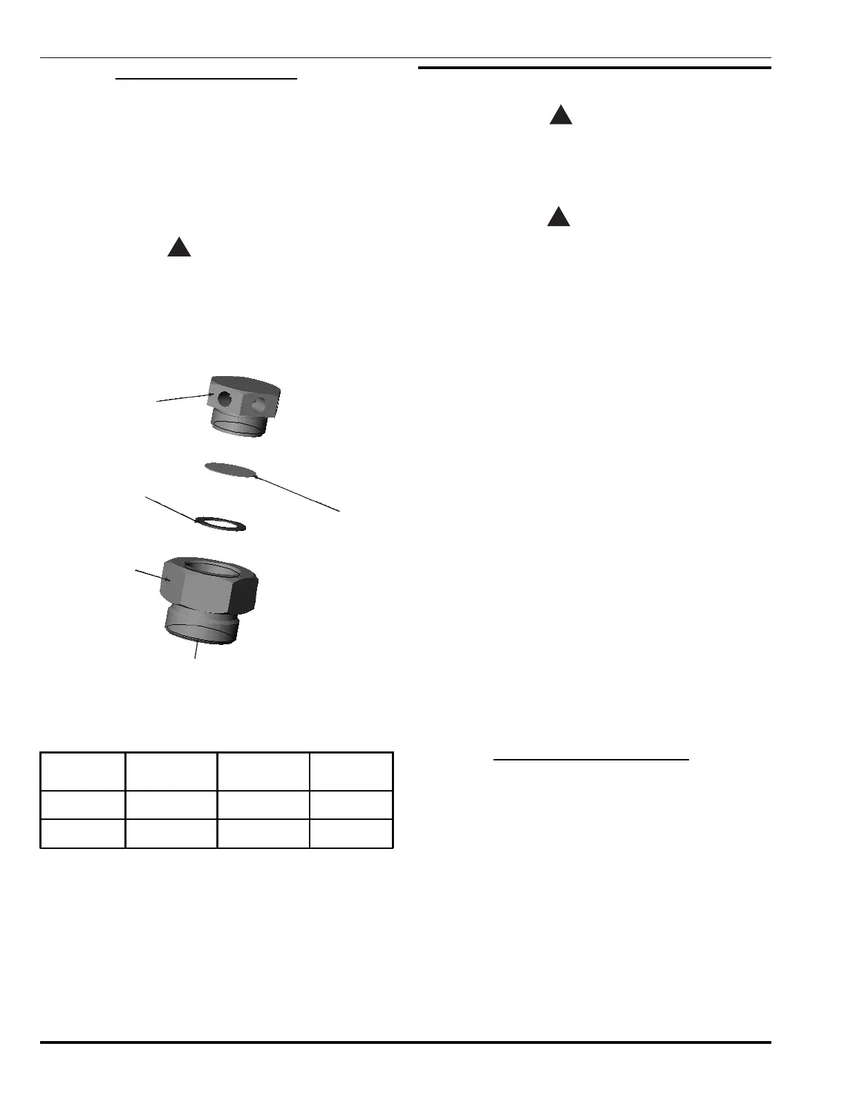
6-2.7 Safety Disc Replacement (3")
The safety disc for the 3" valve is located on the cylinder
head, not on the cylinder valve.
1. Remove the safety disc retainer (see Figure 6-5) in-
cluding safety disc and safety disc washer from the
cylinder body. Discard the safety disc and washer.
2. Reassemble the safety disc retainer with a new safety
disc and safety disc washer to the valve body. Torque
to the appropriate value listed in Table 6-5.
WARNING
!
Never install any type of disc other than
specified in Table 6-5 for the corresponding
cylinder. Installing the incorrect disc could
result in a violent rupture of the cylinder and
serious injury.
Safety Disk Retainer
06-235926-001
Safety Disk Washer
06-118185-001
Burst Disk
06-235926-001
Safety Disk
06-118184-001
Burst Disk Holder
06-236063-001
Figure 6-5. Burst Disc
Table 6-5. Safety Disc Replacement Table (3")
Cylinder Size Safety Disc P/N Torque Value PSIG @ 70° F
600 lb. 06-118184-001 90 ft. lb. 800-975
900 lb. 06-118184-001 90 ft. lb. 800-975
6-3 RECHARGING FM-200 CYLINDERS
CAUTION
!
FM-200 cylinders may require retest before
recharging (see Paragraph 5-5 for details on
cylinder retest). FM Approval is based upon the
usage of factory filled FM-200 cylinders.
WARNING
!
Under no circumstances while performing
either cylinder recharge or leak test, should a
charged cylinder be allowed to stand freely
without either the charging apparatus attached
or the safety cap installed. Whenever these
devices are not installed, a charged cylinder
must be securely clamped to a rigid structure
capable of sustaining the full thrust that would
result should the valve inadvertently open. The
clamping device and supports must be capable
of withstanding a thrust force of 1800 lb. (816.5
kg). This approximates the thrust force
generated out of the FM-200 cylinder valve
outlet on a full, wide-open discharge.
FM-200 charging equipment consists of an FM-200 stor-
age container, piping adapter, control valves, strainer, pres-
sure gauge, flexible hoses, seating adapter, recharge
adapter, pump, regulated nitrogen supply, scale and inter-
connecting plumbing. Recharge equipment must be suit-
able for the purpose intended and must be compatible with
FM-200. A typical FM-200 charging system schematic is
shown in Figure 6-6.
Note: During recharge, cylinder pressure gauge is not to
be used to determine charging pressure.
Locate the charging equipment in a clean,
well-ventilated area near the FM-200 supply and
cylinder storage. There should be sufficient
room for moving the cylinders to and from the
charging equipment.
6-3.1 Charging Equipment Installation
Before assembling the charging equipment, apply Permacel
No. 412D Teflon
®
tape to all pipe threads.
 Loading...