6-690-FM200M-000 September 2004
FM-200
®
ECS Series Engineered Fire Suppression Systems
FM-2OO return line
optional salvage
connection
15
23
24
22
19 20
21
15
15
29
10
Strainer
FM-200 Agent
14
9
12
11
13
15
8
4
1
27
28
7
30
15
29
flex hose
FM-200 liquid supply line
4
6
5
2
26
3
cylinder
scale
flex hose
N
2
18
16
17
nitrogen line
1
P
R
25
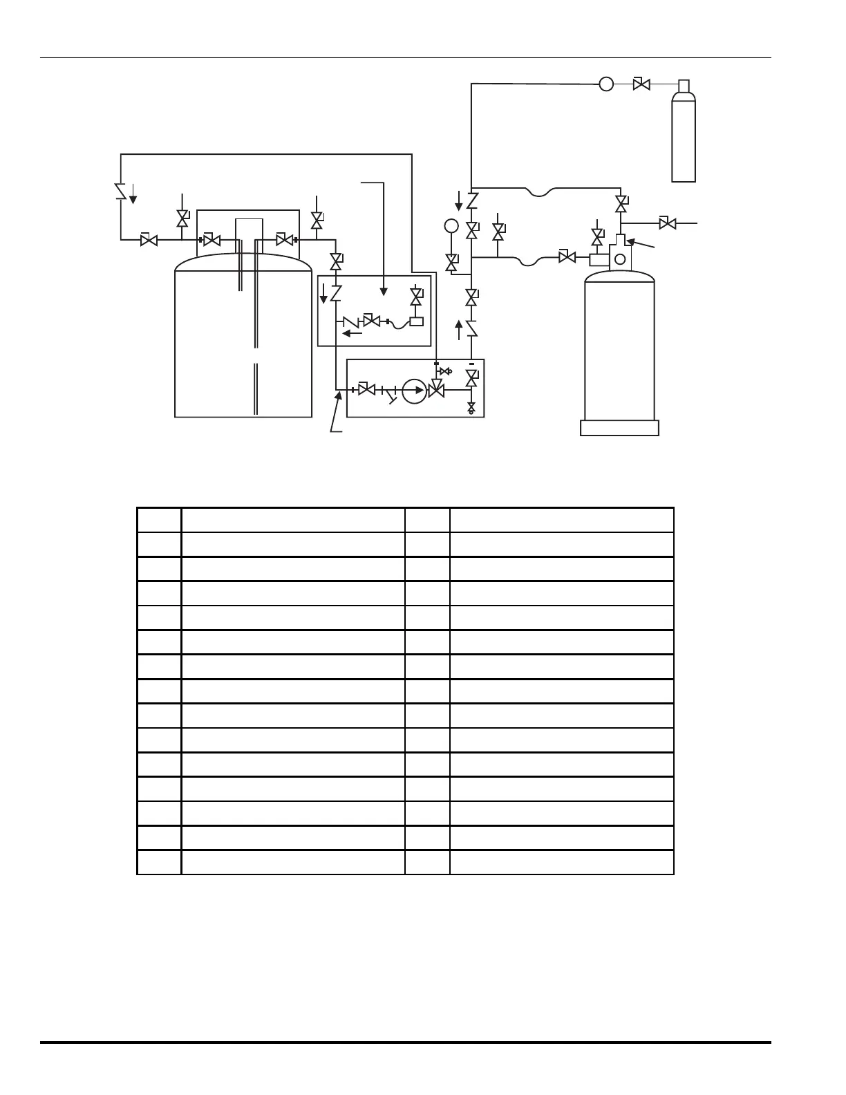
Figure 6-6. Typical FM-200 Charging System Schematic
Table 6-6. Typical FM-200 Charging System Schematic
1
Recharge Adapter
16
Ball Valve
2
Seating Adapter
17
Regulator
3
Scale
18
Nitrogen Cylinder
4
Vent Valve - Recharge
19
FM-200 Shipping Container, Liquid
5
Vent Valve - Seating
20
Vent Valve
6
Ball Valve
21
Ball Valve
7
Ball Valve
22
FM-200 Shipping Container, Vapor
8
Ball Valve
23
Vent Valve
9
3- Way Valve
24
Ball Valve
10
Ball Valve
25
FM-200 Shipping Container, Vapor
11
Ball Valve
26
FM-200 Agent Storage Container
12
Safety Relief, Liquid
27
Ball Valve, Gauge
13
Safety Relief, Vapor
28
Master Pressure Gauge
14
Pump
29
Ball Valve
15
Check Valve
30
Vent Valve
 Loading...