6-890-FM200M-000 September 2004
FM-200
®
ECS Series Engineered Fire Suppression Systems
The pressure in the agent container is significantly affected
by fill density and temperature. At elevated temperatures,
the rate of increase in pressure is very sensitive to fill den-
sity (see Figure 1-1). If the maximum fill density is exceeded,
the pressure will increase rapidly with temperature increase
so as to present a hazard to personnel and property. Ad-
herence to the limits on fill density and pressurization lev-
els will prevent excessively high pressures from occurring
if the agent container is exposed to elevated temperature,
minimizing the possibility of an inadvertent discharge of
agent through the pressure relief device.
Note: When charging more than one FM-200 cylinder, it
may be advantageous to leave the pump (Item 14)
running. In this case, when a cylinder is full, rotate
the 3-way valve (Item 9) to direct the flow back to
the supply tank through the FM-200 return line. To
resume charging operations, return the 3-way valve
(Item 9) back to the Filling position.
To change the FM-200 shipping container (Item 25)
close cylinder valves (Items 19 and 22) close valves
(Items 21 and 24). Carefully open vent valves
(Items 20 and 23) to bleed pressure. Disconnect
charging lines from FM-200 supply cylinder. Posi-
tion new FM-200 supply cylinder in place. Connect
charging lines to new FM-200 supply cylinder, en-
suring vapor and liquid lines are connected to
proper valves. Close vent valves (Items 20 and 23).
Open valves (Items 21 and 24).
6-3.3 FM-200 Cylinder Leak Test
WARNING
!
Clamp FM-200 cylinder securely in place. The
clamping device and supports must be capable
of withstanding a thrust force of 1800 lb.
(816.5 kg). This approximates the thrust force
generated out of the FM-200 cylinder valve
outlet on a full, wide open discharge.
CAUTION
!
FM-200 cylinder leak tests must be conducted
in a well-ventilated area, away from the
charging station so as not to be influenced by
extraneous FM-200 vapors released during the
filling operations. Kidde recommends the
Yokogawa Type H25C leak detector for FM-200,
with the Yokogawa Type LS-20 leak standard
for FM-200 for calibrating the leak detector.
1. Warm up the leak detector for 30 minutes before pro-
ceeding with Step 2.
2. Calibrate the detector against the LS-20 leak standard
by holding the probe about 1/8 in. (3 mm) away, and
noting the meter deflection for the leakage allowance
of the standard. Maximum allowable leak rates are
shown in Table 6-8.
3. Remove the safety cap from the discharge outlet. Blow
nitrogen on the surface where the plug was removed.
4. Move the probe back and forth slowly about 1/8 in.
(3 mm) away from all potential leak points (such as the
discharge outlet area, pilot check, valve bonnet, su-
pervisory pressure switch connection, safety outlet, liq-
uid level indicator, valve-to-cylinder connections, gauge
and container welds).
5. Meter deflections greater than indicated during cali-
bration are considered excessive and will be cause
for rejection.
6. Replace the safety cap immediately after the test.
7. If excess leakage is detected, salvage the FM-200
agent, perform the required maintenance on the con-
tainer and recharge.
8. After the leak test is complete, reassemble the protec-
tion cap to the actuation port of the valve assembly.
Unclamp the cylinder.
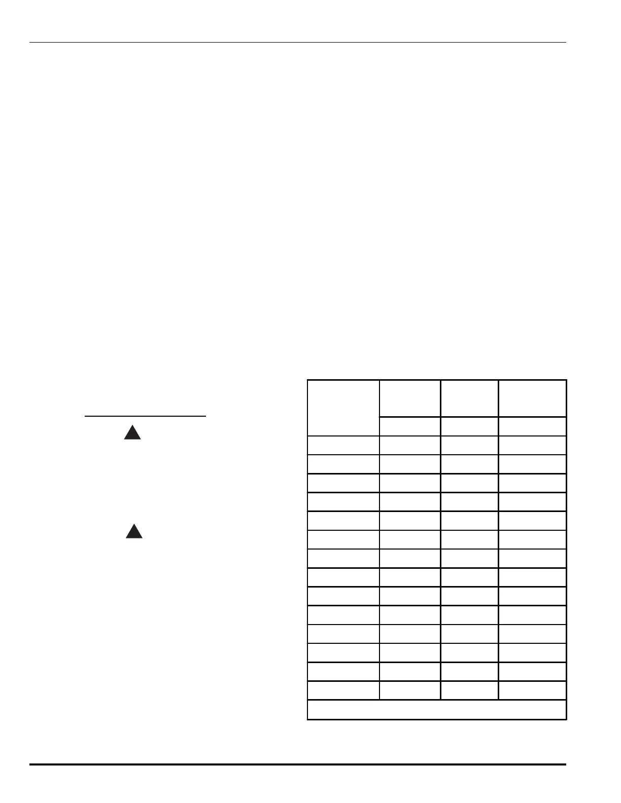
Table 6-8. Maximum Permitted Leakage Rates
Part Number
Cylinder Size
Cylinder Fill
Weight
Maximum
Allowable
Leakage
lb. lb. oz./yr.
90-100010-001 10 6-11 0.11
90-100020-001 20 9-23 0.20
90-100040-001 40 17 - 40 0.37
90-100070-001 70 30 - 70 0.67
90-100125-001 125 54 - 125 1.20
90-100200-001 200 86 - 200 1.81
90-100201-001 * 200 86 - 200 1.81
90-100200-101 200 86 - 200 1.81
90-100201-101* 200 86 - 200 1.81
90-100350-001 350 150 - 350 3.34
90-100351-001* 350 150 - 350 3.34
90-100600-001 600 258 - 600 5.74
90-100601-001* 600 258 - 600 5.74
90-10090X-001 900 390-900 8.68
*Note: Includes liquid level indicator
 Loading...