Chapter 2: Design and installation
Alarmline II Digital Linear Heat Sensor Cable Technical Manual 11
Area coverage
In applications where the sensor cable is installed for general area coverage (as
an alternative to point type heat detectors), the positioning of the sensor cable
typically follows the applicable local standards or approvals. The sensor cable is
typically installed at ceiling height and laid out so that sufficient coverage is
provided (see Figure 2 below).
Maximum spacing between cable runs typically follows the same limits as normal
point type heat detectors and as defined by applicable local standards, as shown
in the table below.
Table 9: Maximum spacing between cable runs
Maximum spacing
5839 7.5 m (24.5 ft.)
9 m (30 ft.)
9 m (30 ft.)
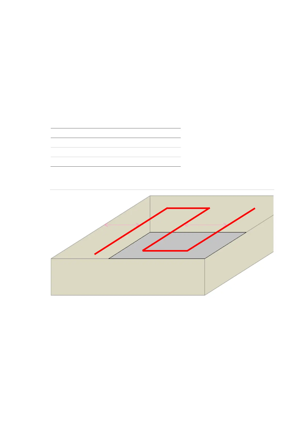
Figure 2: Distributed sensor cable for general area coverage
Other design recommendations for general area coverage systems:
• Selection of the appropriate sensor cable type is critical to ensure correct
performance. The selection of the cable will be based on the maximum
possible ambient temperature within the risk area and the alarm temperature
of the cable.
• The recommended total area coverage for a single Alarmline II Digital
detection zone shall be no more than 2000 m
2
(21,528 ft
2
).
d
1
– Spacing of sensor cable from the wall (d
1
= (d
2
/2))
d
2
– Spacing between sensor cable runs
 Loading...