Chapter 2: Design and installation
16 Alarmline II Digital Linear Heat Sensor Cable Technical Manual
The position of the alarm resistor in the circuit is critical – it must be located at
the start of the sensor cable. If using an interposing cable this allows the
interposing cable to be monitored for open and short circuit faults only. Only
when the sensor cable operates (short circuits) will the alarm resistor be
introduced to the circuit activating an alarm at the control equipment.
5. The sensor cable must be installed only in the protected area and will be
monitored for open circuit faults (short circuit on the sensor cable indicates an
alarm). The correct temperature sensor cable must be selected for the
application to prevent false alarms.
6. End-of-line monitoring device. This allows the control panel to monitor the
integrity of the circuit completing the circuit and allowing sufficient current flow
from the positive to negative terminals. The end-of-line monitoring device
must be located at the end of the sensor cable and the value will be specified
by the control equipment manufacturer. In the majority of cases the end-of-
line devices will be supplied with the control panel.
Interposing or leader cable
The sensor cable must be installed only in the area that it is protecting. In some
applications, you’ll need to use an interposing or leader cable to connect the
sensor cable to the monitoring equipment.
An approved fire-rated interposing or leader cable should be used and, when
connecting the interposing or leader cable to the sensor cable, an IP66/67 rated
junction box should be used. The maximum length of the interposing/leader cable
will vary based on the cross-sectional area, as shown below.
The following maximum lengths of interposing or leader cable are based on the
maximum length of sensor cable (3000 m or 9842 ft.).
Table 11: Maximum length of interposing or leader cable
able cross section Maximum length
mm
2
(18 AWG) 2,500 m (8,200 ft.)
mm
2
(16 AWG) 3,500 m (11,500 ft.)
mm
2
(14 AWG) 6,000 m (20,000 ft.)
mm
2
(12 AWG) 9,500 m (31,000 ft.)
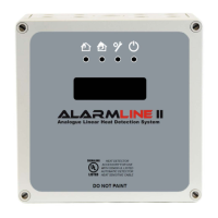
Digital Location Control Unit
For applications where long lengths of sensor cable are installed such as cable
tunnels, road tunnels, and conveyor belts use a Digital Location Control Unit to
detect the location of the alarm activation along a length of cable. A maximum of
3 km of Alarmline II Digital Sensor Cable can be attached to the Digital Location
Control Unit.

 Loading...