Chapter 2: Design and installation
Alarmline II Digital Linear Heat Sensor Cable Technical Manual 15
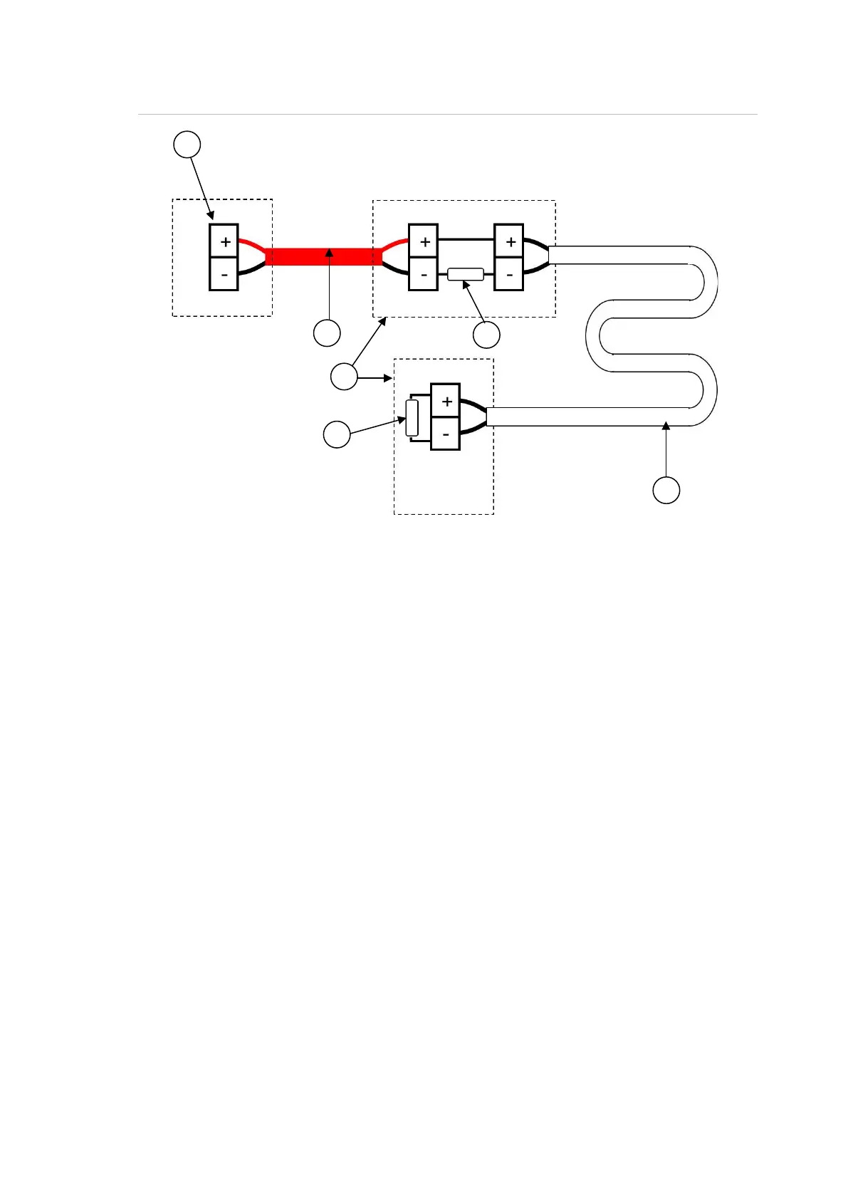
Figure 3: Connecting to a fire alarm control panel
1. Connection terminals for monitored input (whether this is a conventional
detection zone or a loop interface two terminals are provided). This input will
monitor for changes in the resistance of the circuit to determine the presence
of an open circuit or an alarm condition (short circuit).
2. Interposing or leader cable (the sensor cable must be installed only in the
area that it is to protect). If the control equipment or interface is to be mounted
remotely to the protected area, then a suitable two-core fire-rated cable can
be used to make the connection between the two locations (“Interposing or
leader cable” on page 16).
3. Suitable junction boxes should be used when terminating the sensor cable
(for example, Ex junction boxes for hazardous areas). The diameter of the
sensor cables range from 3.6 to 4.5 mm – be sure to select the correct size
glands for junction boxes.
4. Alarm resistor. Monitored inputs will monitor for changes in the resistance of
the circuit connected to it and different resistance values will indicate different
events.
Conventional fire alarm panels and loop interfaces will have a specified alarm
resistor value which must be fitted in series with the sensor cable for the
system to activate an alarm condition. The alarm resistor value will vary
dependent on the control equipment/interface and will be specified by the
equipment manufacturer.
 Loading...