2 / 2 P/N 3101025-EN • REV 03 • ISS 16NOV15
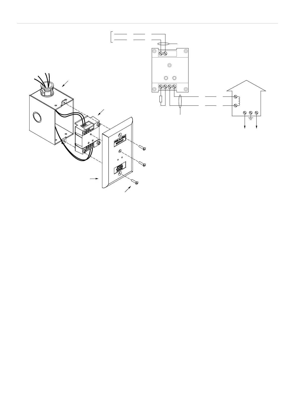
Figure 1: CTM installation wiring diagram
[1] Power-limited and supervised for opens, shorts, and ground faults
[2] Nonpower-limited and supervised for opens and ground faults only.
26 Ω, max. 4.4 A, max.
[3] Use end-of-line resistor value required by the notification appliance
circuit
[4] NAC output signal must be compatible with the input rating of the
local energy type master box.
21
1234
+
–
ActiveNormal
Public fire alarm
reporting system
Local energy type
master box
+
–
+
–
+
–
EOLR [3]
ActiveNormal
From dedicated notification
appliance circuit [4]
Compatible electrical box
CTM
Wall plate
Screws
14.5 Ω
trip coil
[1]
[2]

 Loading...
