Chapter 5: Installation
104 P/N 3101890-EN • REV 006 • ISS 21JUN18
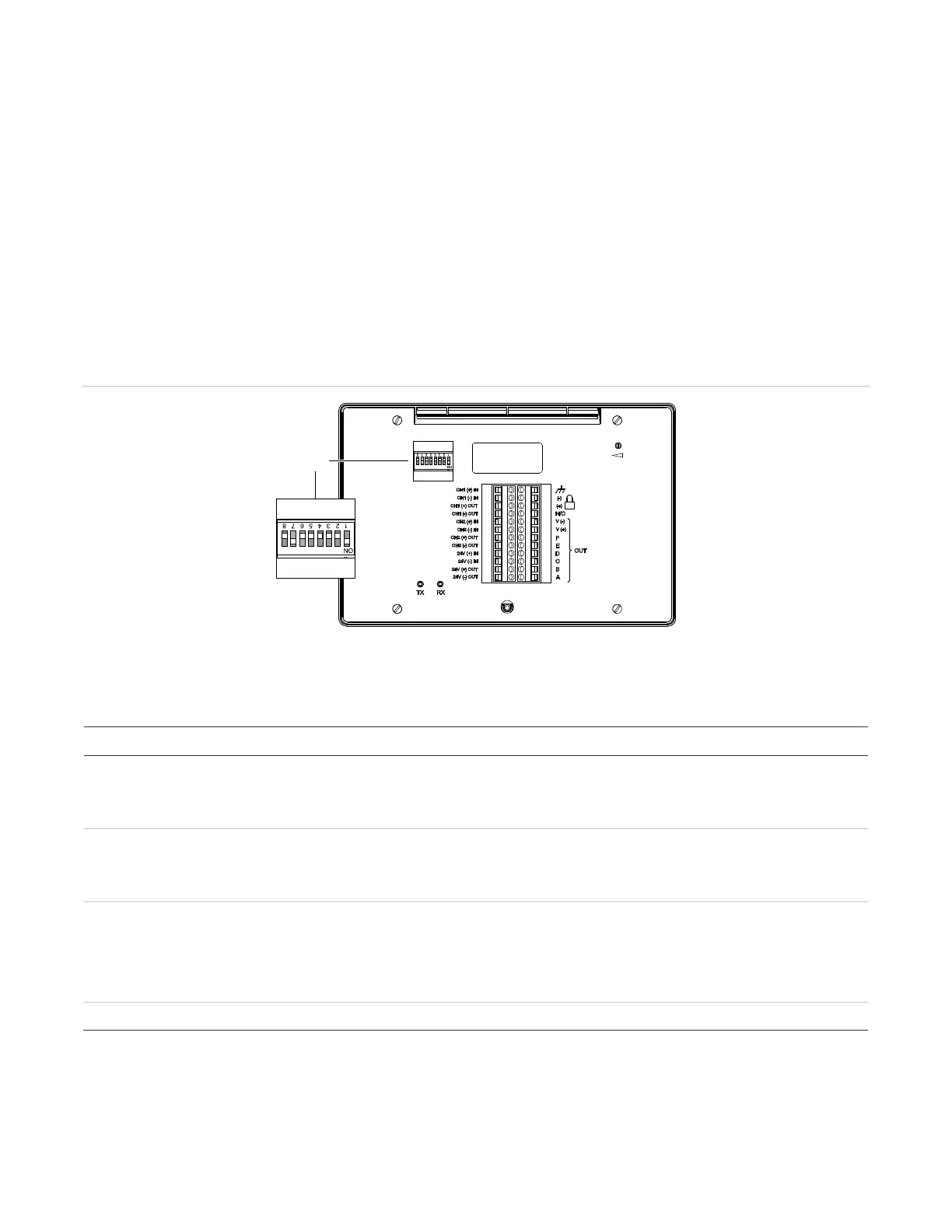
R-Series and K-R-Series annunciator DIP switch settings
For correct operation, the R-Series / K-R-Series remote annunciator must be configured with a unique address
and must be in communication with the VM-1 fire alarm control panel. These settings are configured from the DIP
Switch SW1 on the back of the annunciator (see Figure 36). Refer to Table 35 for descriptions of each Switch
SW1 segment (switch). Refer to Table 36 on page 105 for examples of address settings.
For complete annunciator installation instructions, see the R-Series Remote Annunciators and Expanders
Installation and Operation Guide (P/N 3100969-EN) or K-R-Series Remote Annunciators and Expanders
Installation and Operation Guide (P/N 3102382-EN).
Note: DIP Switch SW1 segment 7 (SW1-7) must be set to On for annunciator communication with the VM-1 fire
alarm control panel. In the On position, R-Series / K-R-Series remote annunciators and GCI(-NB) graph
annunciators support Class B and Class A wiring, Style 6.
Figure 36: R-Series / K-R-Series annunciator rear view showing DIP SW1 segments
(1) DIP Switch SW1
Table 35: DIP Switch SW1 settings
Description
-1 to SW1-5 Annunciator address.
The annunciator address (in binary). The factory setting is for address 2. See
Table 36 for examples. Possible values are 1 to 31.
-6 Baud rate.
OFF = 9600 baud (factory default setting)
On = All other baud rates
-7 Annunciator circuit type.
OFF = Circuit supports Class B and Redundant Class B wiring
On = Circuit supports Class B and Class A wiring
Note: SW1-7 must be set to On.
-8 Not used.