Chapter 7: Service and troubleshooting
P/N 3101890-EN • REV 006 • ISS 21JUN18 131
VM-DACT Dual Line Dialer Card troubleshooting
LED indicator diagnostics
LINE 1 and LINE 2 LEDs on the VM-DACT provide diagnostic information. See the tables below for a description
of the LEDs and their dialing and data transmission states.
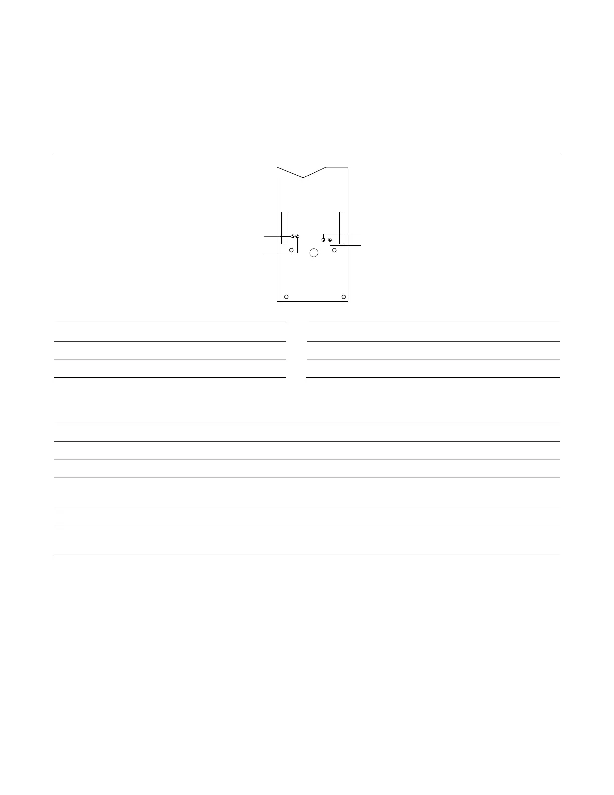
Figure 43: VM-DACT LED indicators
Description Label
1 Indicates line 1 telephone activity RX Indicates receive activity
2 Indicates line 2 telephone activity TX Indicates transmit activity
Table 48: VM-DACT LINE 1 and LINE 2 LED states
state LINE 1 description LINE 2 description
There is no activity There is no activity
LINE 1 has been seized LINE 2 has been seized
Dialer or modem data is being passed
on LINE 1
Dialer data is being passed on Line 2
(modem data is passed only on LINE 1)
LEDs) The application code or configuration code is downloading from the CPU or VM-CU
Reflects ringing on LINE 1 (flashing
pattern detected)
N/A (LINE 2 does not have ring detection)
Cellular capture module problems
To troubleshoot problems with a cellular capture module, refer to the installation manual received with the
module.
Audible diagnostics
Obtain an audio amplifier device locally for listening to the distinctive sounds associated with dialing, receiving
handshakes, transmitting data, and receiving acknowledgements. Place a 0.1 μF, 200 V or greater capacitor in
series with one of the leads. Alternately, you can use a lineman’s handset in monitor mode.
During downloading from a remote computer, you will hear the distinct sound of modems establishing a
connection, and then a series of rapid chirps as data is transmitted.
LINE
1
LINE
2
RX TX
LINE 1
LINE 2
RX
TX