Chapter 7: Service and troubleshooting
148 P/N 3101890-EN • REV 006 • ISS 21JUN18
Isolating circuit and device problems
The process of isolating a problem on a signaling line circuit is similar to that used on a conventional fire alarm
Initiating Device Circuit (IDC). An accurate and complete wiring diagram of the loop is the best troubleshooting aid
available. When used in conjunction with the information provided by the control panel, you can easily isolate
open conditions or defective devices. The loop shown in Figure 45 on page 148 will be used to illustrate basic
troubleshooting techniques.
Note: When troubleshooting Class A loops, disconnect the circuit from the return (loop A) terminals and
temporarily jumper both loop A terminals to the respective loop B terminals. You can then troubleshoot the circuit
as a Class B circuit.
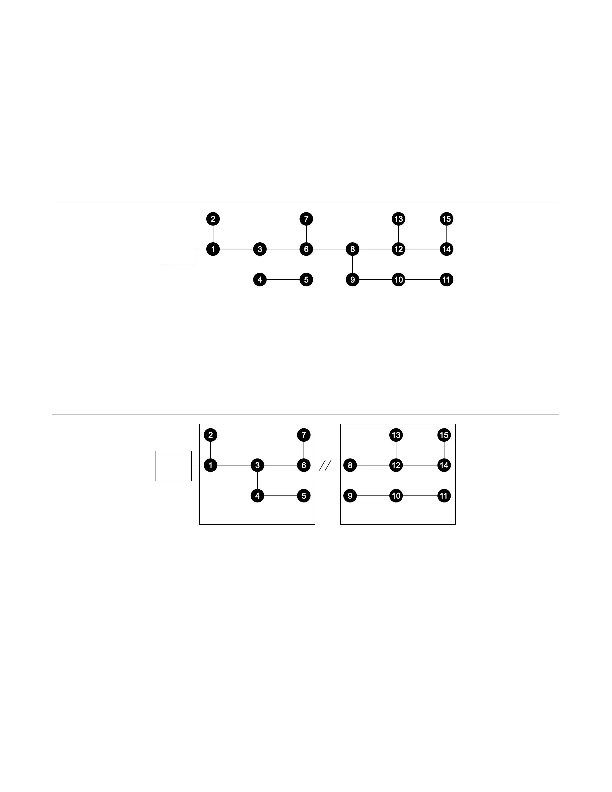
Figure 45: Normal signaling line circuit topology
(1) Loop controller
Open circuit conditions
On a circuit with an open fault, the modules communicate with devices up to the break and the LCD screen
displays a trouble condition for all devices beyond the break. Figure 46 shows devices 1 through 7 continuing to
operate and devices 8 through 15 reporting device troubles.
Figure 46: Open fault on the loop
(1) Loop controller
(2) Break in the loop
(3) Devices in trouble
(4) Devices operating normally
In Figure 46, a wire break or intermittent connection between devices 6 and 8 is the most probable cause of the
failure. Other possible causes include a device failure in devices 9 through 15, failure to define them in the loop
controller’s database, or failure to define them correctly in the VM-CU.
Short circuit conditions
Short circuit conditions require selective isolation of portions of the loop controller circuit to systematically narrow
down the fault’s location. A shorted circuit typically shows a trouble condition on all devices, as shown in
Figure 47 on page 149.