Chapter 7: Service and troubleshooting
150 P/N 3101890-EN • REV 006 • ISS 21JUN18
• GSA-MCC1 riser selector
• GSA-MCC1S riser selector
• Portable handset and receptacle (P/N 6830-3 and 6833-4) telephone module
• Remote telephone and wall box, Break Glass (P/N 6830-4 and 6831-1, or 6831-3) telephone module
• Remote telephone and wall box, Nonbreak Glass (P/N 6830-4 and 6831-2, or 6831-4) telephone module
Note: For instructions on configuring a four-state telephone, refer to the installation sheet supplied with the GSA
input or output module.
Ground fault conditions
Ground fault conditions require selective isolation of portions of the loop to systematically narrow down the fault’s
location. A loop with a ground fault (approximately 10 kΩ or less to ground) causes the Ground Fault LED on the
control panel user interface to indicate. The fault conditions can occur on the loop, the 24 VDC smoke power
circuit, or the input circuits to the loop controller on the CPU and the VM-SLCXB loop controller. The general
location of a ground fault can be determined by viewing a Trouble Report (see “Status reports” on page 40) or by
indications and messages on the control panel user interface (see Table 60).
Table 60: Ground fault indications
ser interface indications Ground fault location
LED is on but no device trouble
shows on the LCD screen
• Loop controller circuit
• 24 VDC smoke power circuit
LED is on and a device trouble
message with the device address
shows on the
screen
Positive leg of the input circuit for the device
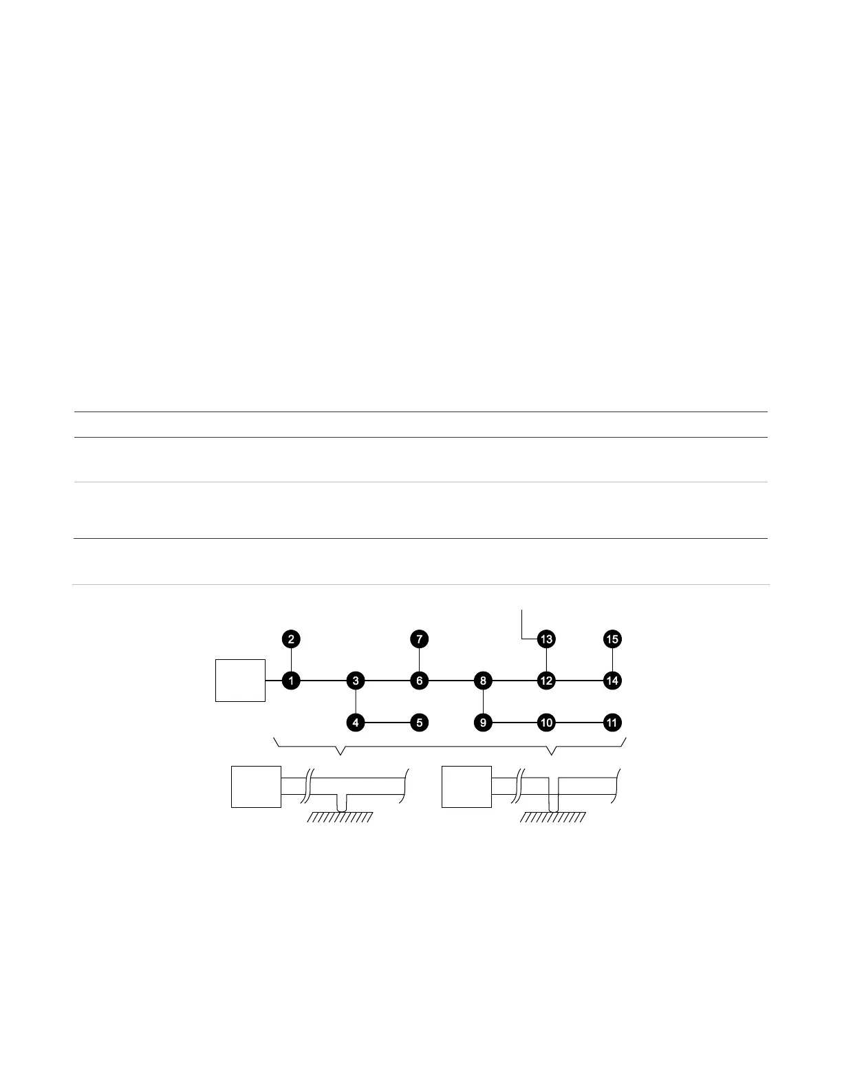
Figure 49: Loop ground faults
(1) Loop controller
(2) Ground fault location
(3) Positive ground fault
(4) Negative ground fault
To isolate the ground fault, open the suspect loop (both conductors) at a location that will disconnect
approximately 50% of the installed devices as shows in Figure 50. A similar technique is used on smoke power or
module input circuits.