Chapter 7: Service and troubleshooting
P/N 3101890-EN • REV 006 • ISS 21JUN18 151
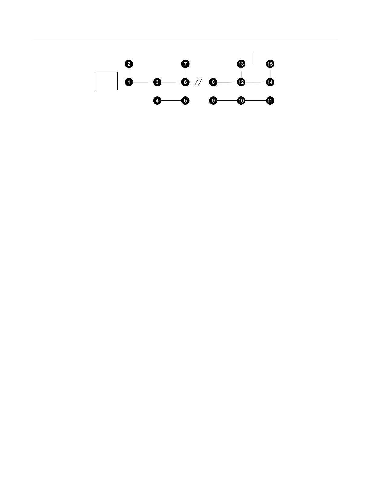
Figure 50: Ground fault isolation
(1) Loop controller (ground fault LED Off)
(2) Both conductors open insolates the ground fault
(3) Ground fault
After opening the loop, if the Ground Fault LED goes out, the ground fault is located on the portion of the circuit
that has been disconnected. If the t LED remains on and no devices restore, the short has been isolated to the
first 50% of the circuit.
Reconnect the previously isolated portion of the circuit. If during the first isolation process, the Ground Fault LED
went off, open the loop at a location electrically farther from the loop controller and repeat the analysis. If during
the first process the Ground Fault LED remained on, open the loop at a location electrically closer to the loop
controller, and then repeat the analysis. Continue increasing or decreasing the number of devices on the opened
loop leg until you isolate the single device or wire segment causing the problem.
Notes
• The ground fault detection circuitry requires approximately 30 to 40 seconds to respond when the fault is
removed.
• The VM-1 control panel performs a ground fault test for 2 seconds at 18-second intervals. If the system is
working properly, the voltage between earth ground and logic negative should be between 12.3 VDC and 16.8
VDC during the 2-second test. The system reports a ground fault when the voltages are less than 12.3 and
more than 16.8 VDC. In a non-faulted system, the voltage outside the 2-second test period may float
randomly. If the system is faulted, then the voltage is likely to be a fixed value such as 3 or 19 VDC.
Substituting devices
When substituting a known good detector or module in place of a suspect device, one of two scenarios can take
place.
1. If the substituted device is the same model as the suspect device, the system accepts it with no further
operator action. When the substituted device is installed, the system goes into trouble. When the quantity of
devices defined on the circuit is reached, the system automatically remaps the circuit, stores the revised
information, and returns to normal. This process may take a few minutes.
2. If the substituted device is a different model than the suspect device when the device count is correct, the
loop controller automatically remaps the circuit. A trouble occurs at the address of the suspect device as the
result of a map fault, because the known good device’s parameters differ from those of the removed suspect
device. You must accept the parameters of the known good device to remove the fault.
Detectors
When one or more devices are removed from a loop for servicing, as shown in Figure 51 on page 152 the control
panel LCD screen displays a trouble condition for each device. If the control panel is connected to the computer
running the VM-CU, the Current Status tab on the V-Series Status / Diagnostics window indicates a trouble
condition.
 Loading...


