Chapter 3: Operating instructions
56 P/N 3101890-EN • REV 006 • ISS 21JUN18
Control-indicating module
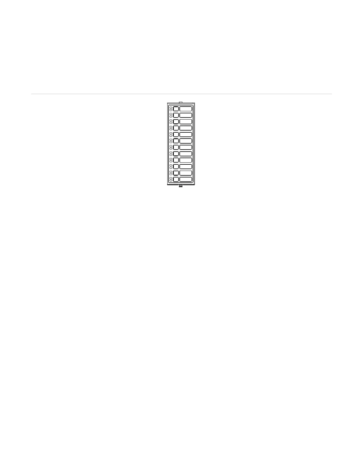
The D12LS-VM Control-Indicating Module provides additional operator interface capability. Up to three modules
can be mounted on any of the last three card address spaces on the electronics chassis. A blank insert is
provided for labeling the LEDs and switches. The module consists of 12 groups of two LED-switches. The top
LED can be configured in the VM-CU to amber, red, blue, or green. The bottom LED is amber.
Figure 13: D12LS-VM Control-Indicating module
The buttons on the control-indicating module use one of three available operating modes that are database
configured.
• Toggle: The state of the button changes each time the button is pushed (i.e. “off” to “on” or “on” to “off”).
Toggle buttons are commonly used to control two-state operations such as on/off, open/close, speaker select,
telephone select, etc.
• Interlocked: Three adjacent toggle buttons that operate as a group. Pushing any button in the group turns the
output of the other two buttons “off” and turns its own output “on.” The interlocked mode is commonly used for
hands-off auto control of HVAC systems. An interlocked button in the “on” state can be turned “off” without
activating a second button by pressing the “on” button a second time. The output of the “on” button remains
on, during panel reset. It must be manually returned to “Auto” when no longer required.
• Momentary: The button is “on” only while pressed by the operator. Momentary buttons are typically to issue
brief commands. Example uses for momentary buttons include a lamp test, function reset, and test sequence.
The command is issued only while the button is pressed.
You may find multiple button modes on a single control-indicating module. Consult your site-specific
documentation for additional information.
Disabling and enabling control-indicating module
Disabling a control-indicating module isolates it from the system. While disabled, changes to the module’s state
are not processed. When the module is disabled, the Disable LED on the user interface indicates and a Disabled
Active event shows in the Trouble Queue.
Enabling a control-indicating module re-establishes it as part of the system. When enabled, any changes in state
that occurred while the module was disabled are processed.
To disable a control-indicating module:
1. Access the Main Menu, and then select Disable.
2. Select Card, and then enter the panel and card addresses.
3. Enter the access level password.
 Loading...


