Kieback&Peter GmbH & Co. KG
Tempelhofer Weg 50, 12347 Berlin/Germany
Telefon: +49 30 60095-0, Telefax: +49 30 60095-164
www.kieback-peter.de, info@kieback-peter.com
Datasheet 2.70-10.411-01-EN
BMR410
Issue 2011-04-27
A
Änderungen vorbehalten - Contents subject to change - Sous réserve de modifications - Reservado el derecho a modificación - Wijzigingen
voorbehouden - Con riserva di modifiche - Innehåll som skall ändras - Změny vyhrazeny - Zmiany zastrzeżone - Возможны изменения
-
A változtatások jogát fenntartjuk -
保留未经通知而改动的权力
Product Description
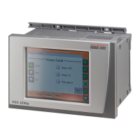
BMR410 Controller
Application
The BMR410 is a DDC controller for regulating,
controlling, monitoring and optimizing heating, ventilation
and air conditioning systems.
The BMR410 also has a fieldbus to allow for flexible
enhancement with input and output modules, as well as
with room control modules.
With an integrated Ethernet interface, the BMR410 has a
built in web server to facilitate visualization, remote
control and data backup over a web browser without the
need of any additional software.
Parameterization can be carried out using the BMRTool, the SI Tool or the PS4000.
Additional main features of the BMR410:
■ Native BACnet® in accordance with DIN EN ISO 16484-5 (BACnet® server functionality);
facilitates communication with the BMS by Ethernet or modem.
■ The BMRTool allows you to configure the controller quickly and easily. Plant macros are set to configure the
BMR410 completely, set the associated BMR software objects, configure the parameters and assign the input
and output signals.
■ Simple turn-knob operation with illuminated display
■ Weekly schedule and annual schedule
■ Trend data can be saves and visualized
■ Code keys for quick display and adjustment of plant values at different access levels;
customer-specific plaintext for every parameter
■ Can be operated in 12 languages (Czech, Dutch, English, French, German, Hungarian, Italian, Latvian, Polish,
Russian, Spanish and Swedish)
■ 3 closed-loop control circuits for heating or 2 for ventilation, which can be extended by hardware and software
objects
■ Malfunction message logging with time and date
Content Page
Important Information Regarding Product Safety ..................................................................................................2
Item........................................................................................................................................................................3
Technical Data.....................................................................................................................................................3
Accessories (not included in delivery) .................................................................................................................4
Dimensions..........................................................................................................................................................5
Connectable fieldbus modules.............................................................................................................................6
Connection...........................................................................................................................................................6
Fieldbus Power Supply........................................................................................................................................8
Installation..............................................................................................................................................................9
Opening the Housing ...........................................................................................................................................9
Removal...............................................................................................................................................................10