EasyManua.ls Logo

Kikusui PCR4000LE User Manual

Kikusui PCR4000LE
134 pages
To Next Page IconTo Next Page
Page #1 background imageLoading...
Page #1 background image
PCR500LE
PCR1000LE
PCR2000LE
PCR3000LE
PCR4000LE
PCR6000LE
PCR9000LE
Users Manual
AC Power Supply PCR-LE series
PART NO. IB02390H
Oct. 2017
Checking the Package Contents 3
Features 3
About the PCR-LE Documentation 4
PCR-LE Series models 6
Precautions Concerning Installation 6
Precautions When Moving the Product 6
Handling the Terminal Block Tray (PCR1000LE - PCR9000LE) 7
Connecting the PCR500LE Power Cord 8
Connecting the power cord (PCR1000LE - PCR 9000LE) 9
Turning the Power On 9
Connecting the Load 10
- Basic -
Front Panel 13
Rear Panel 15
Panel Operation Basics 16
Selecting the Output Mode 20
Setting the Output Voltage 21
Setting the Frequency 26
Turning Output On and Off 26
Displaying Measured Values 28
Limit Values and Protection Functions30
Setting Limits31
Using Protection Functions 36
Using Memory 38
- Advanced -
Using the Synchronization Function 45
Using the Voltage compensation Function 46
Using Power Line Abnormality Simulations 51
Using the Sequence Function 54
Using the Harmonic Current Analysis Function 63
Generating Special Waveforms (Waveform bank) 64
Setting the Output Impedance 65
Setting Soft Starts (The voltage rise time) 65
Fixing the Internal Vcc 66
Selecting the Response 66
Using the Power Management Functions 67
Controlling the Output Using External Analog Signals 68
- Specications -
Main Unit Specications 77
Option Specications 84
Outline Drawings 86
- Appendix -
Glossary 91
Operating Characteristics 93
About the output and the load 94
Peak hold current measurement 102
Sequence tutorial 103
Option 115
Factory Default Settings (Initialization) 122
Maintenance 125
Troubleshooting 126
Alarms and Trouble 128
Error Message 131
Index 132

Table of Contents

Other manuals for Kikusui PCR4000LE

Question and Answer IconNeed help?

Do you have a question about the Kikusui PCR4000LE and is the answer not in the manual?

Kikusui PCR4000LE Specifications

General IconGeneral
Rated Output Capacity4 kVA
Power Rating4000 VA
Input Frequency50 Hz / 60 Hz
Cooling MethodForced air cooling
Output Power4000 W
Rated Output VoltageSingle Phase 100 V / 200 V
Output Voltage Range0 to 135 Vrms / 0 to 270 Vrms
Output VoltageAC
Rated Output Current40 A / 20 A
Output Current Range0 to 40 A / 0 to 20 A
Load Regulation0.1% of F.S.
Line Regulation±0.1%
Ripple Voltage0.3 Vrms
Current Accuracy±0.2% of full scale
Ripple and Noise0.3 Vrms
Response Time1 ms
Operating Temperature Range0 to 40 °C
Storage Temperature Range-10 to 70 °C
Input Voltage200 V to 240 V AC
Efficiency85%
Dimensions430 mm (W) x 221 mm (H) x 550 mm (D)

Summary

Documentation Structure and Supporting Manuals

User's Manual Sections Overview

Overviews of the manual's core sections covering operation, specs, and advanced features.

Installation and Handling Precautions

Installation Environment and Moving Safety Guidelines

Guidelines for proper installation location, ventilation, and safe product movement.

Power Cord Connection Procedures

Connecting the PCR500LE Power Cord

Instructions for connecting the power cord to the PCR500LE, including safety checks.

Power Cord Connection for Larger Models

Power cord connection details and cable specifications for PCR1000LE to PCR9000LE.

Powering the Unit On and Off

Power On Procedure and Safety Checks

Steps to safely turn the unit on, including pre-checks and understanding the initial display.

Power Off Procedure and Settings Retention

How to turn the unit off and notes on how settings are retained after power cycles.

Connecting the Load to the Unit

Output Terminal Block Connection

Instructions for wiring the load to the output terminal block, including wire preparation and safety.

Front-Panel Outlet Connection (PCR500LE)

Specific procedures for connecting loads to the PCR500LE front-panel outlets.

Connecting Load Cables (PCR1000LE - PCR9000LE)

Load Cable Connection Procedure for Larger Models

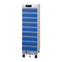
Steps for connecting load cables to the output terminal block for larger PCR-LE models.

Connecting the Load (Continued)

Front-Panel Outlet Connection Details

Further information on connecting loads to front-panel outlets and associated current limits.

Basic Operation: Front Panel Overview

Identifying Front Panel Components

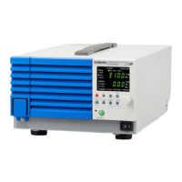
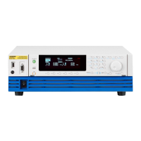
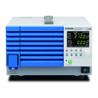
Identifies major components and sections of the PCR-LE Series front panel.

Rear Panel Layout and Connectors

Identifying Rear Panel Connectors and Slots

Identifies all connectors, slots, and ports located on the rear panel of the unit.

Panel Operation Basics

Control Panel Detachment and Attachment

Instructions for detaching and reattaching the control panel for flexible usage.

Understanding the Display Screen

Display Screen Areas and Function Key Explanation

Explains the display sections (Status, Entry, Function Key) and how function keys are documented.

Interface Navigation and Settings Management

Covers Home position, canceling settings, ENT wait state, and restoring factory defaults.

Panel Operation Basics (Continued)

Specifying Values via Keypad or Rotary Knob

Methods for entering numerical values for settings using the front panel controls.

Selecting the Output Mode

Output Mode Setup Procedure

How to select between single-phase, three-wire, and two-phase output modes.

Setting the Output Voltage

Setting the Output Voltage Mode (AC, DC, AC+DC)

How to select the output voltage mode (AC, DC, or AC+DC) and its implications.

Output Voltage Mode Setup Procedure

Step-by-step guide for selecting the desired output voltage mode.

Setting the Output Voltage (Continued)

Setting the Output Voltage Range (L and H)

How to select the voltage range (L or H) and its effect on current and voltage specifications.

Setting the Output Voltage Value

How to set the specific AC, DC, or AC+DC output voltage value.

Output Voltage Setup Procedure

Detailed Steps for Setting AC and DC Voltages

Detailed steps for setting AC and DC voltages using the front panel interface.

Setting the Output Voltage (Continued)

Single-phase, Three-wire Output Voltage Setup

Procedures for setting AC and DC voltages, including phase differences, for single-phase, three-wire output.

AC+DC Mode Voltage and Phase Settings

How to set AC/DC voltages and phase differences in AC+DC mode.

DC Mode Voltage Setup

Procedures for setting DC voltages using phase and line voltage options.

Three-phase Output Voltage Setup Procedure

Setting AC and DC Voltages for Three-Phase Output

Steps for setting AC and DC voltages for three-phase output, including phase differences.

Setting the Output Frequency

Frequency Setup Procedure

How to set the output frequency in AC and AC+DC modes.

Turning Output On and Off

Output Control Operation and Safety Warnings

How to control the output state, including safety warnings and power-on state configuration.

Displaying Measured Values

Setting Aperture Time for Measurements

How to adjust aperture time to improve measurement stability and accuracy.

Voltage Display Options (RMS, Peak, Average, Line)

How to switch the voltage display between different modes like RMS, Peak, and Line voltage.

Limit Values and Protection Functions Overview

Overview of Limit Functions and Protection Mechanisms

Overview of the product's limit functions and protection mechanisms like OVP, UVP, and Overload.

Setting Limits: Voltage and Frequency

Voltage Upper and Lower Limits Setup

How to set voltage limits to prevent operations outside safe ranges.

Frequency Upper and Lower Limits Setup

How to set frequency limits to ensure operation within specified ranges.

Setting Limits (Continued): Current Limits

Current Limit and Peak Current Limits Setup

How to set the current limit, positive peak, and negative peak current limits.

Setting Limits (Continued): Action on Current Limit Exceedance

Action Configuration When Current Limit is Exceeded

How to configure the unit's action (trip or control) when the current limit is exceeded.

Setting Trip Time for Current Limit Exceedance

Setting Output Turn-Off Delay for Current Limits

How to set the time delay before the output turns off when the current limit is exceeded.

Using Protection Functions

Input Voltage Drop and Overheat Protection

How input voltage drop and overheat protections function and trigger alarms.

Overload, UVP, and OVP Protection Settings

How overload, UVP, and OVP protections activate and how to configure their settings.

Internal Semiconductor Protection (OCP) and Alarm Management

OCP Function and Alarm Time Setting

How OCP protects internal components and setting the alarm time for OCP activation.

Using Internal Memory for Settings Management

Storing Configurations to Internal Memory

Step-by-step guide for saving settings like frequency, voltage, and waveform banks.

Recalling Configurations from Internal Memory

Step-by-step guide for loading saved settings from internal memory.

Saving Data to USB Memory Devices

Procedure for Saving Settings to USB

Procedure for saving internal memory, panel settings, simulations, and sequences to a USB drive.

Recalling Settings from a USB Memory Device

Procedure for Loading Configurations from USB

Procedure for loading configurations and waveform banks from a USB drive.

Wiring Hard and Soft Sensing Functions

Using Power Line Abnormality Simulations

Power Line Abnormality Simulation Setup Procedure

How to set parameters for simulating power failures, voltage dips, and pops.

Executing and Stopping Power Line Abnormality Simulations

Running and Stopping Simulations with Status Signals

How to run and stop simulations, including status signal outputs and polarity settings.

Editing Sequence Steps

Sequence Step Configuration Details

5: Jump Function in Sequences

Editing Sequence Steps (Continued)

Setting Sequence Conditions and Execution Control

Executing, Pausing, and Stopping Sequences

How to run, pause, and stop sequences, including conditions that prevent execution.

Setting Soft Starts (Voltage Rise Time)

SIGNAL I/O Connector and External Control Wiring

Controlling Output On/Off via External Contacts

Controlling Sequence Execution/Stop via External Contacts

Clearing Alarms via External Contacts

Shutting Down the Output via External Contacts

Specifications: Main Unit - Input (AC rms)

Key Input Specifications Summary

Key input specifications including voltage, frequency, apparent power, and current ratings for the AC mode.

Main Unit Specifications (Continued)

AC Mode Output Specifications

Detailed output specifications for AC mode, covering voltage, current, and power capacity.

DC Mode Output Specifications

Detailed output specifications for DC mode, including voltage, current, and power capacity.

AC+DC Mode Output Specifications

Detailed output specifications for AC+DC mode, covering combined AC and DC parameters.

Main Unit Specifications (Continued)

Limit and Protection Function Default Settings

Table of factory default settings for all voltage/frequency limits and protection functions.

Rated Output Current Characteristics (Derating)

About the Output and the Load

About the Output and the Load (Continued)

Rated Output Current in DC/AC+DC Mode

Sequence Tutorial (Continued)

Voltage Sweep and Frequency Sweep Sequences

Switching Steps at Specific Phase Angles

Suddenly Changing the Phase

Suddenly Changing the Phase (Continued)

Phase Sweep Function for U Phase

Line Voltage Dip Sequence Example

Factory Default Settings (Initialization)

Restoring Factory Default Settings Procedures

Procedures for returning all or specific settings to their factory default values.

Maintenance Procedures

Troubleshooting: Control Panel and Output Issues

Troubleshooting: Protection Function Alarms

Guidance for resolving alarms related to OHP, Overload, Current Limit trips, and Phase settings.

Troubleshooting: Output and Protection Issues (Continued)

Troubleshooting (Continued): Output and Load Meter Issues

Troubleshooting: Output Cannot Be Turned On

Steps for resolving issues where the output cannot be turned on or the load level meter is dimly lit.

Alarms and Trouble Overview

Understanding Protection Functions and Indicators

Explains protection functions, alarms (ALM-xx), and trouble indications (TRBL-xx).

Corrective Action: Alarm Codes

Alarm Code Descriptions and Corrective Actions

Detailed descriptions and corrective actions for various alarm codes like OVP, OCP, and UNIT FAIL.

Corrective Action: Trouble Codes

Confirming Power Units in Trouble and Error Messages

Related product manuals