Xsede®
2
Part 3095953, Revision -
Assembly Instructions
Proper product installation, in accordance with these instructions, is the responsibility of the installing agent. If you have
any questions concerning these instructions, please call Kimball Customer Care.
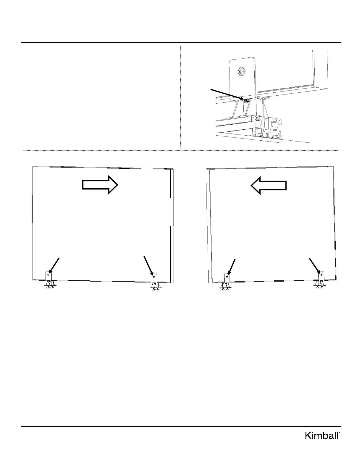
Figure F
6. If screens are setting at an angle, loosen connector bolts and
nuts holding brackets and screen together using (2) M4
Allen key/drives. See Figure E.
7. Once connector bolt/nut are loosened, locate M8 set screws
underneath channel of screen bracket on both sides. See
Figure F for set screw location. Follow Figure G for
alignment. If screen is leaning to the right, tighten set
screws on opposite side of bracket. If screen is leaning to
the left, tighten set screws on opposite side of bracket. To
loosen and tighten set screws, use M4 Allen key provided
in bench base parts box.
8. Sight down screens one last time before proceeding to next
step.
9. Once screen alignment is set, tighten connector bolts and
nuts together using (2) M4 Allen drive/keys. Note: don’t
over-tighten or screens will lean.
M8 Set
Screw
Figure G
SCREEN TILTING RIGHT
(TIGHTEN LOOSEN SET
SCREWS ON OPPOSITE
SIDE)
CONNECTOR
BOLT (LOOSEN;
M4 ALLEN KEY)
CONNECTOR
BOLT (LOOSEN;
M4 ALLEN KEY)
CONNECTOR
NUT (LOOSEN;
M4 ALLEN KEY)
CONNECTOR
NUT (LOOSEN;
M4 ALLEN KEY)
SCREEN TILTING LEFT
(TIGHTEN LOOSEN SET
SCREWS ON OPPOSITE
SIDE)
 Loading...