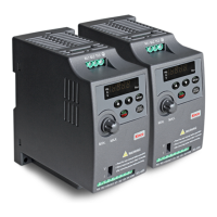
Mini type VFD of CV20 series
Thank you for using CV20 series Variable Frequency Drive made by Kinco Automation.
CV20 satisfies the high performance requirements by using a unique control method to achieve high
torque, high accuracy and wide speed-adjusting range. Its anti-tripping function and capabilities of
adapting to severe power network, temperature, humidity and dusty environment exceed those of
similar product made by other companies, which improves the product’s reliability
noticeably;Without PG connector, strong speed control, flexible input/output terminal, pulse
frequency setting, saving parameters at power outage and stop, frequency setting channel, master and
slave frequency control and so on, all these satisfy various of high accuracy and complex drive
command, at the same time we provide the OEM customer high integration total solution, it values
highly in system cost saving and improving the system reliability.
CV20 can satisfy the customers’ requirements on low noise and EMI by using optimized PWM
technology and EMC design.
This manual provides information on installation, wiring, parameters setting, trouble-shooting,
and daily maintenance. To ensure the correct installation and operation of CV20, please read this
manual carefully before starting the drive and keep it in a proper place and to the right person.
Unpacking Inspection Note
Upon unpacking, please check for:
Any damage occurred during transportation;
Check whether the rated values on the nameplate of the drive are in accordance with your order.
Our product is manufactured and packed at factory with great care. If there is any error, please contact
us or distributors.
The user manual is subject to change without notifying the customers due to the continuous process
of product improvements
VFD model rule
CV20 – 4T– XXXXG–U–000
Production introduction:
General specifications
Rated voltage and
frequency
4T:3-phase,380V~440V AC; 50Hz/60Hz
2S:Single-phase,200V~240V;50Hz/60Hz
1S:Single-phase, 100~120V; 50/60HZ
4T: 320V~460V AC;2S:180V~260V; 1S: 90~132V
Voltage tolerance<3%; Frequency: ±5%
4T:0~440V;2S:0~240V;1S:0~240V
0Hz~300Hz (0~800HZ customizable)
G type: 150% rated current for 1 minute, 180% rated
current for 10 seconds;
Space vector PWM modulation
Digital setting: Max frequency ×±0.01%;
Analog setting: Max. frequency ×±0.2%
Digital setting: 0.01Hz;
Analog setting: Max frequency×0.1%
Manual torque boost :0%~30.0%
4 patterns: 1 V/F curve mode set by user and
3 kinds of torque-derating modes (2.0 order, 1.7 order, and
1.2 order)
Linear acceleration/deceleration,
Four kinds of acceleration/deceleration time
Limit current during the operation automatically
to prevent frequent overcurrent trip
Operation Panel, Terminal, CommunicationControl,
Supportswitching between these control channesl.
Digital, Analog Voltage/current setting.
Support main and auxiliary setting(“+”,”-”, “min”, “max”)
Display setting frequency, output frequency, output voltage,
output current and so on, about 20 parameters.
Keys lock and
function selection
Lock part of keys or all the keys.
Define the function of part of keys
Open phase protection (optional), overcurrent protection,
overvoltage protection, under-voltage protection, overheat
protection, over-load protection and so on.
Indoor, installed in the environment free from
directsunlight, dust, corrosive gas, combustible gas, oil
mist, steam and drip.
Derated above 1000m, the rated output current
shall be decreased by 10% for every rise of 1000m
-10℃~40℃, derated at 40℃~ 50℃
Air cooling, with fan control.
Introduction of CV20 series:
External dimension:
CV20-2S-0004G~ CV20-2S-0015G/ CV20-1S-0002G~ CV20-1S-0007G
CV20-4T-0007G~CV20-4T-0022G
Mechanical parameters
VFD model
(G: Constant torque load;
L: Draught fan and water
pump load)
External dimension and (mm)
Operation Button Description
Increase the value or function
Decrease the value or function
Enter or Exit the programming status
In panel operation mode, run the vfd by the first pressing; stop vfd by the second
pressing. In VFD error status, reset the error by pressing
Short pressing to shift data or function code. Hold pressing(more than 1s) to enter
function code or save the changed value
-Wiring can only be done after the drive’s AC power is disconnected, all the LEDs on the operation
panel are off and waiting for at least 5 minutes. Then, you can remove the panel.
-Wiring job can only be done after confirming the charge indicator on the right bottom is off and the
voltage between main circuit power terminals + and - is below DC36V.
-Wire connections can only be done by trained and authorized person
-Check the wiring carefully before connecting emergency stop or safety circuits.
-Check the drive’s voltage level before supplying power to it, otherwise human injuries or equipment
damage may happen.
-Check whether the Variable Speed Drive’s rated input voltage is in compliant with the AC supply
voltage before using.
-Dielectric strength test of the drive has been done in factory, so you need not do it again.
-Refer to chapter 2 on connected braking resistor or braking kit.
-It is prohibited to connect the AC supply cables to the drive’s terminals U, V and W.
-Grounding cables should be copper cables with section area bigger than 3.5mm2, and the grounding
resistance should be less than 10Ω.
-There is leakage current inside the drive. The total leakage current is greater than 3.5mA, depending
on the usage conditions. To ensure safety, both the drive and the motor should be grounded, and a
leakage current protector (RCD) should be installed. It is recommended to choose B type RCD and
set the leakage current at 300mA.
-The drive should be connected to the AC supply via a circuit breaker or fuse to provide convenience
to input over-current protection and maintenance.
Single-phase 220V(R/L1, S/L2) or 3-phase 380VAC input terminal
3-phase AC output terminal
Main loop
Control loop
R/L1
S/L2
T/L3
PE
U/T1
V/T2
W/T3
X1
X2
X3
X4
COM
+10V
AI
COM
PE
Ra
Rc
1 3
I
V
AI1
M
Multi-function input 1
Multi-function input 2
Multi-function input 3
Multi-function input 4
Analog input
Programable relay output
3-Phase AC power
Braker
PE for motor
Modbus rtu
RS485
2:+5v
3:485+
4:485-
5:GND
√
×
Note: DIP
switch setting
Arrangement of control circuit terminals is as follows:
It lists the possible faults of CV20. The fault code varies from E001 to E027. Once a fault occurs, you
may check it against the table and record the detailed phenomena before seeking service from your
supplier.
Faults and actions
Possible reasons for fault
Over-current
during
acceleration
Parameters of motor are wrong
Auto-tune the parameters of
motor
Coded disc breaks down, when
PG is running
Check the coded disc and the
connection
Select a higher power drive
V/F curve is not suitable
Check and adjust V/F curve,
adjust torque boost
Over-current
during
deceleration
Deceleration time is too short
The load generates energy or
the load inertial is too big
Connect suitable braking kit
Coded disc breaks down, when
PG is running
Check the coded disc and the
connection
Select a higher power drive
Over-current
in
constant speed
operation
Acceleration /Deceleration
time is too short
Prolong Acceleration/
Deceleration time
Sudden change of load or
Abnormal load
Check the AC supply voltage
Coded disc breaks down, when
PG is running
Check the coded disc and the
connection
Select a higher power drive
Over voltage
during
acceleration
Abnormal AC supply voltage
Too short acceleration time
Prolong acceleration time
Over voltage
during
deceleration
Too short Deceleration time
(with reference to generated
energy)
Prolong the deceleration time
The load generates energy or
the load inertial is too big
Connect suitable braking kit
Over voltage
in
constant-speed
operating
process
Wrong ASR parameters, when
drive run in the vector control
mode
Refer to A5. ASR parameter
setting
Acceleration /Deceleration
time is too short
Prolong Acceleration/
Deceleration time
Abnormal AC supply voltage
Abnormal change of input
voltage
Connect suitable braking kit
Drive’s
control power
supply over
voltage
Abnormal AC supply voltage
Check the AC supply voltage or
seek service
Any of phase R, S and T
cannot be detected
Check the wiring and installation
Check the AC supply voltage
Any of Phase U, V and W
cannot be detected
Check the drive’s output wiring
Check the cable and the motor
Short-circuit among 3-phase
output or line-to-ground short
circuit
Rewiring, please make sure the
insulation of motor is good
Instantaneous over-current
Vent is obstructed or fan does
not work
Clean the vent or replace the fan
Lower the ambient temperature
Wires or connectors of control
board are loose
Current waveform distorted
due to output phase loss
Auxiliary power supply is
damaged or IGBT driving
voltage is too low
Short-circuit of IGBT bridge
Control board is abnormal
IGBT
module’s
heatsink
overheat
Lower the ambient temperature
Rectifier’s
heatsink
overheat
Lower the ambient temperature
Communication port:
None: Standard RS485
A: CAN
Power
0002: 200w
0004: 400w
0015: 1.5kw
……
Power supply
1:100V
2:200V
4:400V
4: 400V
00: Standard model
…..other models
S: Signal phase
T: Three-phase
G: Constant torque
L: Constant power
Top of single-phase/3-phase