UNPACKING
ASSEMBLY & ADJUSTMENTS
UNPACKING
Due to modern mass production techniques, it is unlikely that your King Cananda
P
ower tool is faulty or that a part is missing. If you find anything wrong, do not
operate the tool until the parts have been replaced or the fault has been rectified.
F
ailure to do so could result in serious personal injury.
1. Remove all loose parts from the carton.
2. Remove the packing materials from around the saw.
3. Carefully lift the saw from the carton and place it on a level work surface.
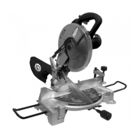
4. The saw has been shipped with the saw arm locked in the down position. To
release the saw arm, push down on the top of the saw arm and pull on the
release knob.
WARNING: Do not lift the saw while holding on to the guards. Use the carrying
handle.
MITER LOCK KNOB
The saw is supplied almost fully assembled, you must assemble the miter lock
knob. Attach the handle by screwing it into position. This handle can be turned to
lock the saw at the desired miter angle. Fig.3.
MITER LATCH
It is necessary to push the miter latch Fig.3 down in order to rotate the turntable.
If the latch is released while the table is being rotated, the table will stop at the
next positive stop. There are positive stops at 0
0
, 15
0
, 22.5
0
, 30
0
and 45
0
to the left
and right.
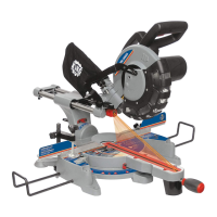
VISE ASSEMBLY
The vertical vise can be installed in two positions on either the left or right side
of the guide fence. Insert the vise rod into the hole in the guide fence and
tighten the vise lock knob on the back of the guide fence to secure the vise rod.
See Fig.4.
EXTENSION WING
ASSEMBLY
The extension wings are installed by inserting them into the mounting holes on
each side of the base. Push them in completely and secure them into place by
tightening the front set screw on each side. See Fig.5.
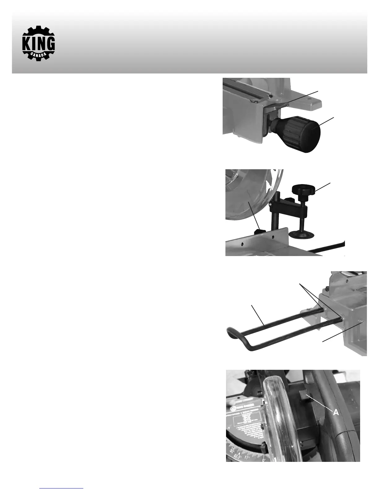
SPINDLE LOCK BUTTON
The spindle lock button (A) Fig.6 prevents the blade in the saw from rotating.
Depress and hold the spindle lock button while installing, changing, or removing
the blade.
Figure 3
Figure 4
Figure 5
Figure 6
Miter lock knob
Miter latch
2 position
Vise system
Vise lock knob
Left Extension wing
Mounting holes
Set screw