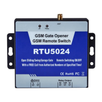
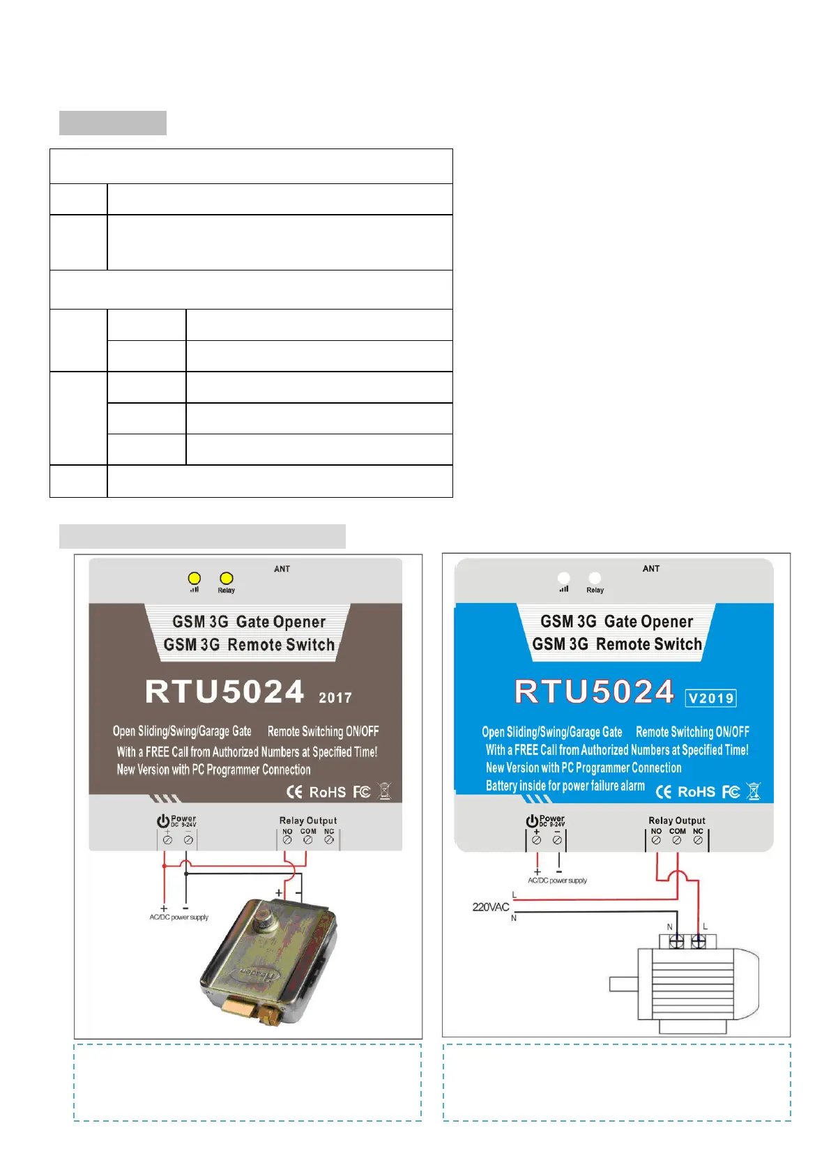
3. Diagram
INDICATORS
Relay ON: Relay closed(ON). OFF: Relay open(OFF)
I
III
Flash per 0.8 second(quickly): registering to cellular network.
Flash per 2 seonds: Normal status.
can’t connect to SIM card or unregistered to the cellular network
Connection Terminals
Power
+
Power supply input,Positive wire(Red).
_
Power supply input,Negative wire(Black).
Relay
Output
NO
Normally Open port
COM
Common port
NC
Normally Close port
ANT
Connect to GSM antenna.
4. Typical wiring connection:
1. RTU5024 for Gate opener:
Power up the RTU5024 and electronic lock by same DC source,the
lock switched ON/OFF by phone call.
2. RTU5024 for remote switch:
The pump switched ON/OFF by phone call. Pump power up by the
grid/electrocity, and RTU5024 power up by AC/DC adaptor.
 Loading...