KING
KMA 20/KH
21
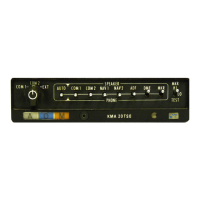
MARKER BEACON
RECElVER/
ISOLATION
AMPLIFIER
(4)
Supply Voltage. Since
the internal
wiring
of all
KMA
20 units
is
the
same,
wiring
for
different
de supply voltages
is not
necessary. Wiring
information
is shown in the
installation
wiring
diagrams.
This
is
also the
case
in the
KR 21,
(5) Ramp Hailer.
(-00/07
Versions)
The location and installation
procedure
for
the
optional
Ramp
hail" speaker, or
alternately a
PA
(passenger
address)
system,
will
be
developed
by the
installing
agency.
When
installation information from
the
airframe
manufacturer
is
available,
it should be
utilized.
A
speaker
having
a power capability of
at
least
8
to
10
watts
and
an impedance of 8 ohms is
required.
If
a
ramp hail
or
PA
speaker
is
not
utilized,
the
EXT
speaker
output
must be
terminated
with a
load
resistor.
This is accomplished
by
terminating
Pin
9 with an external
8
ohm
resistive load. KMA20's
previous
to S/N
11233 had
an internal
resistor
available at
Pin 8.
However,care
must
.be
made
to
make
certain which
resistive load configuration is
in
the KMA
20
to be
installed.
(6) P.A.
(-09/10/11
Versions)
The
-09/10/11
Versions of
the KMA
20
have
an
extra
4
ohm
audio
output
which
is selected by the
mic-selector
switch can
be
used
for passenger
address
system. The
09/10/11 versions have both EXT
(Ramp
Hailer)
and
P.A.
passenger
address
capability.
(7) Transceiver Speaker
Output
Terminations.
Nearly all
current and recent
transceivers
have
a
4 ohm output connection from the
amplifier-modulator
to feed
a
cockpit
speaker
directly when
an isolation amplifier
is
not used.
Since the audio
inputs to
the
KMA
20 use the
500
ohm headphone output
connection,
the 4 ohm output of such
amplifiers
is
not loaded. To
eliminate this
undesireable
condition,
twos ohm
resistors
are
provided
in the
KMA
20
to
perform
this
loading
function.
2.4
INSTALLATIONPROCEDURES
(a) Study
the
installation
to allow adequate
space for installation
of
the connector and
cable.
(b)
After
the location is
determined,
make the panel cutout using the dimensions
shown
in
Figure
2-1
(KMA
20)
or Figure
2-2
(KR 21)
or
Figure
2-3
(KA 40).
(c)
Refer
to
Figure
2-1
(KMA 20)
or
Figure
2-2
(KR 21)
or Figure
2-3
(KA
40)
for the
four
mounting
hole
locations.
Mark,
punch and drill the
holes
in the
aircraft panel
mounting
bracket.
(d)
Secure the
equipment
cover
(mounting
rack) to
the
instrument panel
mounting
(KMA
20
only).
(e)
Fabricate the external cable in
accordance with the installation
wiring
diagram
taking
note of the preceeding
installation
precautions.
(f)
Mount
the
KR
21
in
the panel and connect the
wiring harness.
-CAUTION-
Do
not
overtighten
the
locking
screw.
2.5
MARKER
ANTENNA
INSTALLATION
Any
standard
type
Marker Beacon Receiver
Antenna
meeting TSO
requit
ements
may
be
used
with
the KMA
20
or KR
21.
However,
due to
the possible variations
and sensitivifles of the
antennas,
it is
suggested
that a
flight check be
made after installation
to
determine if the
sensitivity
setting
Page
2-2
Rev.
2, June,
1976