Do you have a question about the Kingspan KoolDuct System and is the answer not in the manual?
Information for fabricators and delivery partners regarding system use and specifications.
Guidelines for selecting and training installation contractors for proper practice.
Essential safety measures for handling, cutting, and working with the product.
Best practices for storing and handling KoolDuct panels and sections to prevent damage.
Details on panel dimensions, facings, and available sizes for various regions.
Defines operational limits, applications, and non-applicable uses for KoolDuct.
Specifies components and materials required for UL listing compliance.
Details required information for designing, fabricating, and installing KoolDuct ductwork.
Outlines the sequential steps for fabricating KoolDuct sections.
Illustrates the construction and sealing of a typical KoolDuct section end.
Describes the use of a straight cutting machine for duct panels.
Details the application of CNC machines for precise cutting of duct components.
Instructions for using a two-bladed jack plane for cutting.
Guidance on using single-bladed small jack planes for specific cuts.
Instructions for using a two-bladed jack plane for 1 3/16" panels.
Guidance on using small jack planes for specific cuts on R-8 panels.
Table detailing maximum spacing for Tiger Clips based on pressure.
Illustrates Tiger Clip placement for ducts at different pressures.
Steps for applying adhesive for pressure classes up to 3 in.w.g.
Instructions for applying aluminum tape for sealing and assembly.
Details the use of the Extended Silicone Tool #444 for sealing.
Provides guidance on silicone bead size and application temperature.
Details cutting along the panel length for straight ducts.
Illustrates the assembly sequence for straight ducts using sealant and tape.
Details cutting along the panel length for straight ducts.
Details cutting along the panel length for straight ducts.
Details cutting along the panel length for straight ducts.
Details cutting along the panel width for straight ducts.
Describes beveling, adhesive, Tiger clips, and tape for panel joints.
Details additional reinforcement requirements for panel joints.
Describes an alternative fabrication method for large ductwork.
Methods for creating end caps for short and long ducts.
Details concentric, eccentric transitions, and splitter requirements.
Details angled, mitred, and radius offset types and their limitations.
Provides dimensions and creasing instructions for eccentric transitions.
Provides dimensions and creasing instructions for concentric transitions.
Illustrates the geometry and dimensions for double offsets.
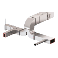
Shows configurations for straight, angle, and boot branch take-offs.
Details methods for small un-flanged take-offs at low pressure.
Provides suggested Tiger Clip placement for small take-offs.
Specifies mechanical fixings for large flanged take-offs.
Details mechanical fix requirements for large round flanged fittings.
Illustrates round take-off spigots with spiral tubes.
Shows methods for installing grilles/diffusers using aluminum profiles.
Instructions for cutting and fitting turning vanes into square elbows.
Details methods for securing turning vanes with silicone or mechanical fix.
Illustrates dimensions and features of symmetric radius elbows.
Provides a schedule for selecting splitters for short radius elbows.
Illustrates dimensions and features of asymmetric radius elbows.
Details sealing interior corners and fastening splitters.
Table of maximum Tiger Clip spacing for elbows and tees.
Explains how to use templates for symmetric and asymmetric elbow layout.
Provides a schedule for splitter selection for this elbow type.
Details the cutting steps using jack planes for this elbow type.
Illustrates dimensions and features of a dynamic Y branch with radius elbow.
Shows the sequence of assembling the Y branch components.
Illustrates dimensions for external flushed Tee branches.
Illustrates dimensions for internal flushed Tee branches.
Shows the assembly sequence for Tee branch components.
Details the steps for assembling a 4-Bolt Flange connection.
Covers bonding the flange and screw types for the connection.
Explains gasket attachment, silicone application, and bolt tightening.
Illustrates various external and internal grip flange profiles.
Details application and pressure limits for 7/8" R-6 grip flanges.
Details application and pressure limits for 1 3/16" R-8 grip flanges.
Instructions for sealing exposed insulation on R-8 grip flanges.
Highlights features like air-tight joints, no adhesive/rivets, and strength.
Explains notching points for external grip flanges.
Details cutting for internal grip flange pieces.
Shows the profile, notching, and installation of grip flanges.
Illustrates the coupling process using grip flange and bayonet cleat.
Details steps and limitations for joining duct segments using Tiger Clips.
Shows various grip and structural flange profiles for component connections.
Details the use of structural profiles as an alternative to grip for 7/8" R-6.
Illustrates flanged and spigotted connections using profiles.
Shows how to connect KoolDuct to fire dampers with break-away joints.
Illustrates connecting ducts to VCDs and FCUs with Tiger Units.
Describes the construction of KoolDuct and installation of pre-fab inspection doors.
Outlines factors determining duct reinforcement needs: size and pressure.
Specifies methods for installing reinforcing bars and panels.
States that all duct shapes and fittings require reinforcement.
Recommends pressure relief dampers for potential over-pressurization.
Details three types of reinforcement systems: tube-encased tube, threaded rod, and inserts.
Lists selection criteria for reinforcing bars for positive pressure.
Lists selection criteria for reinforcing bars for negative pressure.
Explains adding reinforcement based on duct size and pressure.
Schedule for reinforcement based on duct dimension and pressure.
Schedule for reinforcement based on duct dimension and pressure.
Schedule for reinforcement based on duct dimension and pressure.
Schedule for reinforcement based on duct dimension and pressure.
Schedule for reinforcement based on duct dimension and pressure.
Schedule for reinforcement based on duct dimension and pressure.
Practical examples illustrating reinforcement application for R-6 and R-8 ducts.
Methods for reinforcing areas where standard bars cannot be installed.
Guidance on reinforcing end caps based on straight duct schedules.
Principles for supporting KoolDuct ductwork and suitable support types.
Lists components for hangers and supports, and the need for independent support.
Guidelines for maximum spacing between supports for horizontal ductwork.
Specifies minimum sizes for rod, strap, and wire hangers.
Details maximum allowable loads for single hangers based on type.
Guidance on supporting various duct fittings like elbows and take-offs.
Notes on caution labels regarding access and additional loadings for supports.
Illustrates options for supporting vertical ductwork.
Recommends installing supports at the base of vertically oriented ductwork.
Emphasizes determining ductwork weight for proper support selection.
Tables showing duct weight for Grip flange and Bayonet Coupling.
Tables showing duct weight for 4-Bolt Flange coupling.
Tables showing duct weight for Tiger Clip coupling.
Tables showing duct weight for Grip flange and Bayonet Coupling.
Tables showing duct weight for 4-Bolt Flange coupling.
Tables showing duct weight for Tiger Clip coupling.
Recommended dry and non-abrasive cleaning methods for KoolDuct.
Describes installing sensors/controllers and protective plates in ductwork.
Methods for repairing superficial and substantial damage.
Lists preferred finishes for weatherproofing external ductwork.
Discusses painting KoolDuct for decorative purposes and fire performance.
Table showing notch positions for 7/8 inch grip flanges.
Continues table of notch positions for 7/8 inch grip flanges.
Continues table of notch positions for 7/8 inch grip flanges.
Continues table of notch positions for 7/8 inch grip flanges.
Continues table of notch positions for 7/8 inch grip flanges.
Continues table of notch positions for 7/8 inch grip flanges.
Table showing notch positions for 1 3/16 inch grip flanges.
Continues table of notch positions for 1 3/16 inch grip flanges.
Continues table of notch positions for 1 3/16 inch grip flanges.
Continues table of notch positions for 1 3/16 inch grip flanges.
Continues table of notch positions for 1 3/16 inch grip flanges.
Continues table of notch positions for 1 3/16 inch grip flanges.
Checklist for verifying fabrication quality against standards.
Checklist items for couplings, end caps, and reinforcement.
Checklist items for installation, couplings, and take-offs.
Checklist items for vertical/outdoor ducts and health/safety.
Explains the purpose of commissioning an air distribution system.
Details testing procedures and relevant standards for ductwork.
Lists pre-start checks for pressure, dampers, and controls.
Explains the function and installation of pressure relief dampers.
Describes temporary test hole requirements for flow measurements.
Lists references and standards for KoolDuct system and HVAC ductwork.
| Brand | Kingspan |
|---|---|
| Model | KoolDuct System |
| Category | Industrial Equipment |
| Language | English |