--
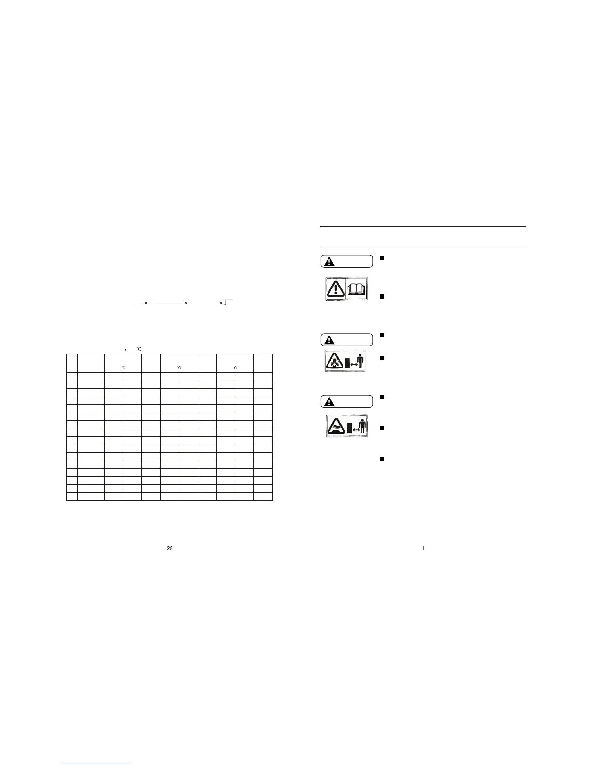
1. SAFETY INSTRUCTION
The generators are designed to give safe and dependable
service if operated according to instructions.
Read and understand the Owner's Manual before operating
the generator. Failure to do so could result in personal injury
or equipment damage.
Please use light diese. Gasoline and pafaffin is not allowed
to use
Exhaust gas contains poisonous carbon monoxide. Never
run the generator in an enclosed area. Be sure to provide
adequate ventilation.
Generator should be earthed with a wire to avoid electric
shock
The muffler becomes very hot during operation and
remains hot for a while after stopping the engine.
Be careful not to touch the muffler while it is hot.
Let the engine cool before storing the generator indoors.
The engine exhaust system will be heated during operation
and remain hot immediately after stopping the engine.To
prevent scalding, pay attention to the warning marks attached
to the generator.
Battery charge should be carried out in the place with good
ventilation. Smoke and spark is forbidden.
Ambient temperature 25
2. The choice of the electric cable
The choice of the electric cable depends on the allowable current of the cable
and the distance between the load and the generator. And the cable section
should be big enough.
If the current in the cable is bigger than the allowable current, it will become over
hot and the cable will be burnt. If the cable is long and thin, the input voltage of
the electric appliance will be not enough, causing that the generator doesn't start.
In the following formula, you can calculate the value of the potential "e".
The relations among of the allowable current, and length, section of the Insulating
cable (single core, multi-core) are as follow:
(Presume that the use voltage is 220V and the potential is below 10V.
Potential (v)
= Current (A) 3
Length
Section area
1
58
1
2
3
4
5
6
7
8
9
10
11
12
13
14
15
No.
Copper
cables model
2
1.5mm
2
2.5mm
2
4mm
2
6mm
2
10mm
2
16mm
2
25mm
2
35mm
2
50mm
2
70mm
2
95mm
2
120mm
2
150mm
2
185mm
2
240mm
Voltage
Drop
mv/M
Single core
Current capacity
(25 )(A)
Voltage
Drop
mv/M
Three cores
Current capacity
(25 )(A)
Voltage
Drop
mv/M
Four cores
Current capacity
(25 )(A)
VV22
20
28
38
48
65
88
113
142
171
218
265
305
355
410
490
YJV22
25
35
50
60
85
110
157
192
232
294
355
410
478
550
660
30.86
18.9
11.76
7.86
4.67
2.95
1.87
1.35
1.01
0.71
0.52
0.43
0.36
0.3
0.25
VV22
13
18
24
32
45
61
85
105
124
160
201
235
275
323
381
YJV22
18
22
32
41
55
75
105
130
155
205
248
292
343
400
480
30.86
18.9
11.76
7.86
4.67
2.6
1.6
1.2
0.87
0.61
0.45
0.36
0.3
0.25
0.21
VV22
13
18
25
33
47
65
86
108
137
176
217
253
290
333
400
YJV22
13
30
32
42
56
80
108
130
165
220
265
310
360
415
495
VV22
20
28
38
48
65
88
113
142
171
218
265
305
355
410
490
Note: The variation of temperature and the laying of cables will influence the current capacity
of cables, the table above is just used for reference.
WARNING
WARNING
WARNING
--
 Loading...