Do you have a question about the Kistler 4503B Series and is the answer not in the manual?
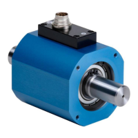
The Kistler Dual-Range Torque Sensor Type 4503B.../BQ... is a precision instrument designed for measuring both constant and variable torques on rotating shafts. It utilizes a strain gauge measuring system with digitalized, wear-resistant signal transmission. The sensor is suitable for applications in laboratories, production, and quality control, offering high accuracy for precision measurements.
The torque sensor consists of a main casting that houses a shaft rotating in bearings. Strain gauges are arranged on the torsion section of the measuring shaft, along with electronics for signal amplification and an A/D converter. Stationary electronics for signal shaping are located in the connection box of the main casting. Power and data transmission between the torque sensor and the evaluation unit occurs via inductive coupling (telemetry). Frequencies from the ISM band (115–130 kHz) are used for power transmission, with PSK modulation for data transfer to the rotor at rates between 360–406 bit/s. Measurement data, including torque, temperature, supply voltage, and EEPROM contents, are transmitted from the torque measuring unit to the evaluation unit via inductive coupling at up to 1.4 MBit/s using the 13.56 MHz ISM band frequency. The sensor features galvanic isolation between the power supply and the torque output signal.
The sensor operates with a supply voltage range of 11–30 VDC, with a power input of less than 10 W. It includes an integral speed sensor, with an optional high-resolution speed/angle measurement sensor providing up to 8,192 pulses/revolution. The output signal for torque is typically 5 V TTL (for speed/angle) and ±5/10 VDC at nominal torque (for voltage output) or 100 kHz ±40 kHz (for frequency output). The sensor offers dual-range measurement capabilities, with specific nominal torque ranges varying by model (e.g., 0.2 to 5,000 N·m for 4503B and 5 to 5,000 N·m for 4503BQ).
Key electrical specifications include:
The sensor offers various measuring ranges, with accuracy classes typically 0.05 or 0.1 for the 4503B and 0.1 for the 4503BQ, including linearity error, hysteresis, and repeatability. Temperature influence on zero point and nominal value is also specified. Load limits for longitudinal and transverse forces are provided, with recommendations to stay within 50% of the maximum permissible load for continuous operation.
The sensor features a 2-color LED that indicates its operating condition:
Taring (setting the zero point) can be performed in three ways:
The RS-232C or USB interface allows communication with a control PC using ASCII commands based on the SCPI-Standard. Parameters for the RS-232C interface are 57600 bits/second, 8 data bits, 1 stop bit, no parity, and no flow control. For the USB interface, these are 921600 bits/second, 8 data bits, 1 stop bit, no parity, and no flow control. The sensor acts as a slave, responding to commands from the master (PC).
The output format for torque measurement values (ASCII decimal, hexadecimal, or binary) can be selected. The sensor supports various configuration commands for setting parameters like scaling range, low-pass filters for torque and speed, taring, number of output pulses, and synchronization of measured values. It also offers absolute/relative angle measurement modes. A secondary output (12-pin connector) can be configured for voltage or frequency output, with adjustable scaling ranges, low-pass filters, taring, voltage swing magnitude, and frequency output zero point/swing magnitude.
The torque sensor must always be mounted with couplings to prevent high lateral forces and bending moments. The housing should be prevented from rotating by a holding lug, but the twist protection must not be rigid to allow slight oscillations. During assembly, ensure no forces exist between the housing and shaft. The opposite shaft end should be supported, and the housing should remain free. For installations with a holding bracket or housing base (GU), the brackets/base must be bolted to the stator, ensuring mounting surfaces are plane and adjusting the shaft assembly according to coupling manufacturer instructions.
Measurement cables should not be run in parallel with high-current or control cables, nor near strong electromagnetic fields. If unavoidable, the cable should be run in a grounded steel shield conduit. Excess cable lengths should be avoided or kept as small as possible, not coiled into a closed ring, to minimize induction. It is recommended to use a differential amplifier input for the output UA/AGND. For cables longer than 10 m, speed signals should be isolated from torque signals.
Kistler Type 4503B... torque sensors are largely maintenance-free.
Common issues and their remedies include:
| Brand | Kistler |
|---|---|
| Model | 4503B Series |
| Category | Accessories |
| Language | English |