Do you have a question about the Kistler 4520A Series and is the answer not in the manual?
Instructions for proper disposal of old electronic instruments.
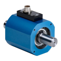
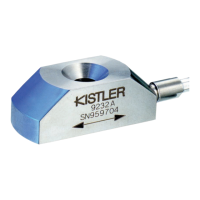
Details the mechanical construction and components of the torque sensor.
Illustrates the electrical connections and signal flow within the sensor.
Demonstrates practical usage scenarios and configurations of the sensor.
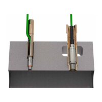
Explains the photo-electric method for speed measurement.
Details the pin allocation for the 12-pin connector.
Provides guidance on proper electrical installation of the sensor.
Lists available cables and connection options for the torque sensor.
Covers methods for mechanically installing the torque sensor, including couplings.
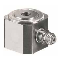
Illustrates various mounting configurations for the torque sensor.
Details application for controlling frictional torque in production processes.
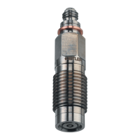
Explains the Torque Measuring Shaft Version RA and its connection.
Describes power supply requirements and signal evaluation methods.
Outlines how to build a basic device for static torque calibration.
Provides a formula and example for calculating lever arm length in calibration.
| Brand | Kistler |
|---|---|
| Model | 4520A Series |
| Category | Accessories |
| Language | English |