Do you have a question about the Kistler 5018A Series and is the answer not in the manual?
Essential safety information for operating the Charge Amplifier and ensuring its long-term, fault-free operation.
Instructions for checking instrument packaging for damage and verifying included items.
Safety precautions for transporting or storing the instrument for extended periods.
Procedure for ensuring the line voltage and instrument's supply voltage setting match before first use.
Details on CE compliance, safety requirements, and EMC standards for electromagnetic compatibility.
Recommendations for reading the manual and keeping it in a safe place for future reference.
List of accessories included with the Charge Amplifier Type 5018A...
Information on optional accessories available for the Charge Amplifier.
Key to abbreviations and special typefaces used in the handbook for clarity.
Explanation of the International System of Units (SI) and its differentiation between base and derived units.
Explanation of how piezoelectric sensors convert mechanical quantities into electrical signals.
Explanation of different measuring modes like DrCo, Short, Medium, and DC (Long) for various applications.
Details on automatic compensation of drift in cylinder pressure signals for engine applications.
Information on the active system for automatic identification and parameterization of sensors.
How the amplifier records working time and cycles, saving them to TEDS.
Guidelines for the proper disposal of old electronic instruments according to environmental regulations.
Information on Kistler's provision of software upgrades and the importance of installing them.
Visual representation of the charge amplifier's internal structure and interconnections of functional blocks.
Description of the amplifier's input stage, charge conversion, and time constants.
Details on the microprocessor controlling the LCD, keypad, communication, and other functions.
Information on the nominal supply voltage, power line filter, and voltage sources.
Overview of a typical measuring chain, including sensor, cable, and charge amplifier.
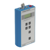
Explains the LCD, LED indicators, control knob, and buttons for interacting with the instrument.
Details the electrical connections and ports on the rear panel of the instrument.
Step-by-step guide for connecting cables, including safety and environmental considerations.
General overview of operating the instrument, including menu navigation and settings.
Provides step-by-step instructions for performing measurements, starting with pressure measurement.
Information about the supplied CD-ROM, PC communication, and software download options.
How to adjust the contrast of the liquid crystal display for better visibility.
Procedure to lock or unlock instrument settings to prevent accidental changes.
How to select and adjust the measuring range of the instrument.
How to set the unit for sensor sensitivity based on the input type.
Instructions for setting the sensor sensitivity value based on the calibration certificate.
How to scale the voltage output range and its relation to measuring range and output in V.
How to activate or deactivate the automatic sensor identification/TEDS function.
Displaying TEDS sensor data, operating hours, cycles, and selecting reference temperature.
How the activity of drift compensation is displayed for engine cycles.
Adjusting the low-pass filter to attenuate high-frequency interference signals.
Defining filter characteristics with cut-off frequency and time constant, including DC (Long) mode.
How the measuring value is displayed in the main menu and further display options.
Selecting the unit of measurement for forces, pressures, accelerations, or torque.
Assigning functions to the [F]-key, such as displaying the measuring value.
Defining whether the measuring cycle is controlled locally or via remote control.
Function to electronically set the input stage of the charge amplifier to zero.
How to store, recall, clear, and reset instrument settings to default values.
Function to display the current measuring value.
Activating a demonstration mode for training purposes, allowing display data transfer to a PC.
Instructions for changing the instrument's display language between German and English.
Checking hardware options and software version loaded on the instrument.
Explanation of various warning and error messages that may appear on the display.
Details on communication protocols, baud rates, and syntax for RS-232C and USB interfaces.
Settings related to TEDS options for sensor identification and operating data saving.
Default settings for TEDS options and activation of the STORE TEDS OP. TIME ON MEASURE function.
Technical specifications for the charge input, including measuring range, error, and drift.
Technical specifications for the voltage or Piezotron input, including measuring range and overload.
Technical specifications for the voltage output, including output range, current, impedance, and interference.
Frequency response characteristics for different measuring modes and LP filter settings.
Time constants for Short and Medium measuring modes based on range FS charge or voltage.
Time constants for the Long measuring mode based on range FS charge.
Specifications for drift compensation operating range and DC offset.
Details on low-pass filters, including cutoff frequencies and delay times.
Information on the remote control connector, pin allocation, input voltage, and delay time.
Details on RS-232C interface, connector pin allocation, cable length, baud rates, and data bits.
Information on the power plug, settable supply voltage, frequency, consumption, and fuses.
Environmental specifications including IP degree of protection, temperature range, vibration, shock, dimensions, and weight.
General precautions to be followed during maintenance and diagnosis procedures.
Explains the slow change in the zero point of the output signal and its potential causes.
Procedures for instrument testing and calibration using voltage sources and capacitors.
Information on Kistler's calibration services, including SCS accreditation and on-site calibration.
Instructions on how to reload firmware into the instrument using a PC.
Step-by-step instructions for safely replacing fuses in the instrument.
Examples of connections for controlling the measuring cycle via remote control.
Diagram illustrating the connection for an RS-232C null-modem cable.
Detailed protocol structure and command codes for RS-232C/USB interface communication.
Explanation of status codes for handshake signals and message formats.
List of event codes generated by the measure card.
List of event codes generated by the CPU.