Do you have a question about the Kistler 5080A Series and is the answer not in the manual?
Information on safe operation, handling, and precautions for electronic equipment.
Instructions for checking instrument packaging for damage upon receipt.
Safety precautions for transporting and storing the instrument to maintain condition.
Details on CE compliance, safety requirements, and EMC considerations.
Recommendations for effectively reading and using the instruction manual.
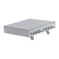
Explanation of the complete type designation and available instrument versions.
List of accessories that are shipped with the Charge Amplifier.
Listing of optional accessories available for purchase for the instrument.
Key to abbreviations, indications, and special typefaces used in the manual.
Explanation of units of measure and the International System of Units (SI).
Explanation of how piezoelectric sensors work and their signal conversion.
Details on automatic drift compensation for cylinder pressure signals.
Guidelines for the proper disposal of electronic equipment at its end of life.
Schematic illustration of the internal functional blocks of the charge amplifier.
Explanation of analog 6-component summing calculator for force-moment calculations.
Detailed description of the amplifier unit, including 'Charge' input and operational amplifier.
Description of the control unit, including keypad, LCD, CAN-Bus, and RS-232C interface.
Information on the nominal supply voltage, frequencies, and internal DC voltage supplies.
Description of a typical measuring chain from sensor to data acquisition.
Overview of multi-component force measurements using dynamometers.
Setup for 3-component force measurement with a 3-channel amplifier and dynamometer.
Setup for 4-component force-moment measurement with a 4-channel amplifier and dynamometer.
Setup for 6-component force-moment measurement with an 8-channel amplifier and dynamometer.
Setup for 5/6-component force-moment measurement with an 8-channel amplifier and measuring hub.
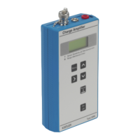
Explanation of the liquid crystal display, LED indicators, and control buttons.
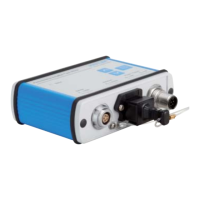
Description of electrical connections and interfaces on the back of the instrument.
Instructions for inserting amplifier modules and interface cards into the chassis.
Procedures for connecting the instrument, including safety and environmental considerations.
Steps for connecting a cable adapter (Type 5435A…) to charge amplifier modules.
Explanation of EMC and ground loop issues and their mitigation.
General information on operating the instrument and its main features.
Description of the instrument's display and navigation through the main menu.
Instructions on how to navigate and operate through the instrument's menus.
Instructions on how to select the operating language of the instrument.
Procedure for entering and saving numerical values for settings.
Step-by-step instructions to guide users through performing measurements.
Example setup for a 3-component force measurement using the amplifier.
Details on signals available from the analog output of the Type 5245 interface.
Guide to performing 6-component force-moment measurements with summation.
Instructions on entering sensor distances for correct summation calculations.
Explanation of correction factors and how to apply them for torque calibration.
How coordinate systems are defined for different applications like 'Wheel Force'.
Signals available from the analog output for the 'General Force' application.
Signals available from the analog output for the 'Wheel Force' application.
Methods for controlling the instrument remotely via MiniDIN or RS-232C interfaces.
Information about the supplied software, its functions, and downloading updates.
How to adjust the contrast of the liquid crystal display for better visibility.
How to use the electronic locking system to prevent accidental maladjustment of settings.
Procedure for selecting the active channel for measurement.
How to calculate force and moment components from multiple amplifier modules.
Notes regarding scaling for summation outputs and required units.
How to enable or disable a channel, affecting its input signal amplification.
Overview of additional menu and setting options available in the instrument.
How to select and set the measuring range for the instrument.
How to vary the measuring range in predefined steps.
How to set the measuring range to any desired value.
How to define the unit of measurement for forces, pressures, etc.
How to set the sensor sensitivity value based on calibration certificates.
How to select the electrical unit (E.U.) for sensitivity and convert it.
How the measuring value is displayed and options for further display.
Definition and operation of the high-pass filter, including its use in DC (Long) mode.
How to attenuate higher frequency interference signals using a low-pass filter.
How to scale the voltage output range and its relation to measuring range.
How the activity of drift compensation is displayed and related information.
How the status of the digital trigger input is indicated on the summation card.
How the chosen parameter set is indicated on the LCD.
How to activate demo mode for training purposes, allowing display data transfer.
Information on selecting the operating language, supporting German and English.
Function to check installed hardware options and software version.
Settings for baud rate and information on RS-232C and USB communication.
How to assign various functions to the [F]-key.
How to control the measuring cycle locally or via remote control.
Steps to control each amplifier module individually via the MiniDIN interface.
How to trigger all amplifier modules simultaneously via the RS-232C interface.
How to control all amplifier modules simultaneously via the RS-232C interface.
Function to electronically set the input stage of the charge amplifier to zero.
Functions for saving, loading, and deleting instrument parameter sets.
Simplifying channel settings by copying them to other channels.
How to save instrument settings into one of the nine available parameter sets.
How to load previously saved parameter sets.
How to clear individual parameter sets or all settings.
How to reset the charge amplifier to its default factory settings.
Function to display the current measuring value.
Menu selection for Piezotron input, defining current source for sensors.
Explanation of various warning and error messages that may appear on the display.
Details on the protocol structure and commands for RS-232C communication.
Detailed description of RS-232C commands, parameters, and status codes.
Explanation of event messages from the measure card and CPU.
Format of event messages, including module number, state, and event code.
List of event codes generated by the measure card.
List of event codes generated by the CPU.
Explanation of the status indicated by the instrument's LEDs.
Technical specifications for the charge input connector and performance.
Technical specifications for low impedance/voltage input on dual mode modules.
Technical specifications for voltage output from charge amplifier/dual mode modules.
Frequency response characteristics for charge amplifier/dual-mode modules.
Time constants for short and medium measuring modes.
Time constants for the long measuring mode.
Specifications for drift compensation, including working range and compensation range.
Specifications for the low-pass filter, including order, cut-off frequency, and tolerance.
Technical specifications for voltage output from the summing calculator interface.
Performance specifications for the Type 5245 interface without the Piezotron option.
Performance specifications for the Type 5245 interface with the Piezotron option.
Pin allocation and connection details for the Fischer connector on Type 5435A.
Specification for the refresh rate of the instrument's LCD.
Technical specifications for remote control via the Type 5067 connector.
Technical specifications for remote control via the Type 5245 interface.
Specifications for RS-232C and USB interfaces for data communication.
Technical details regarding the power supply connection and optional DC supply.
Environmental specifications including IP degree, temperature, vibration, and dimensions.
General precautions to be followed during maintenance and diagnosis procedures.
Explanation of common causes for output signal drift in the instrument.
Procedures for testing and calibrating the instrument's inputs.
How to test the 'Charge' and 'Voltage/Piezotron' inputs using a voltage source.
General information on calibrating the amplifier with reference sources.
Information about Kistler's calibration services, including SCS and re-calibration.
Instructions on how to update the instrument's firmware using a PC.
Step-by-step instructions for replacing fuses in the instrument.
Examples of connections for controlling the instrument via remote control.
Wiring diagram and description for the null-modem cable connection.
Mathematical description of the charge amplifier's transfer function and filters.
Mathematical derivation of the high-pass filter's transfer function.
Introduction to Kistler DynoWare data acquisition software and its use with the amplifier.
Setup and application example for 3-component force measurement with DynoWare.
Setup and application example for 6-component force-torque measurement with DynoWare.