Quick Start Installation
Piezoresistive Amplifier with PiezoSmart
®
Type 4624AK...
4624AK_002-657e-07.16
Contents, front page
1. General Information
2. Scope of Delivery and Accessories
3. Measuring Chain Overview
4. Device Description
5. Voltage Supply and Signal Outputs
6. Connecting Sensors
Contents, back page
7. Explanation of the LEDs
8. Adjusting the Zero Point with Pushbuttons
9. Amplifier Parameterization via Web Interface
10. Installation of the Amplifier
11. Restoring all Settings
12. Repairs at Kistler
13. Disposal Instructions for Electronic Devices
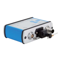
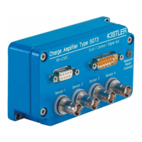
1. General Information
The amplifier Type 4624AK... is a measuring amplifier for
piezoresistive pressure sensors for universal application. As
a result of its automatic sensor identification (PiezoSmart
®
),
the amplifier can be adapted to the connected pressure sen-
sor within a very short amount of time. This results in high
flexibility and process reliability in day-to-day applications.
The present instructions are for rapid commissioning of the
amplifier. Additional technical information can be found in
the data sheet (Doc. No. 003-105). For explanations regard-
ing optional parameterization via the web interface, please
refer directly to the Online Help function.
2. Scope of Delivery and Accessories
Included in the scope of delivery (contents of packaging) are:
• Amplifier Type 4624A
• Installation plate
Connecting cables for signal output and network connection
are available as optional accessories (see data sheet Type
4624AK..., Doc. No. 003-105).
3. Measuring Chain Overview
The amplifier is equipped with the Kistler PiezoSmart
®
sensor
identification feature. This enables the characteristic values of
the sensor to be read out automatically by an electronic data
sheet (TEDS) integrated in the sensor. Various measurement
chains and compatibilities are displayed below.
Foreword
Thank you for choosing a Kistler quality product. Please read
these instructions carefully, so that you can take optimum
advantage of the versatile features of this product.
The information in this document is subject to change at any
time without prior notice. Kistler reserves the right to improve
and alter this product in the interests of technical advance-
ment without being under obligation to notify any individuals
or organizations of such modifications.
©2013 ... 2016, Kistler Group. All rights reserved.
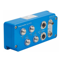
5. Voltage Supply and Signal Outputs
Voltage supply and analog signal outputs for pressure and
temperature are accomplished through the 8 pin socket with
M12x1 locking mechanism (A). The connection can be made
in various ways:
• Standard industrial cable (8 pin, M12x1)
e.g. Kistler Type 4777A5 (5m)
• Connecting cable with BNC signal outputs for pressure
and temperature Kistler Type 1200A179A3 (3m)
• Adapter cable for the connection to a Binder plug in the
case of previous utilization of an amplifier of Type 4618
Kistler Type 4775A0,5 (0,5m)
In the event that a standard industrial cable is used, supply
and signal reception are to be executed in accordance with
the following pin assignment.
Note on voltage supply and GND wiring:
• Voltage supply must range between 10 ... 30 VDC.
Values above 30 VDC could damage the device.
Values below 10 VDC could lead to malfunctions.
• Supply GND (-) must not be connected with Signal
GND (-) of analog signal output.
6. Connecting Sensors
More recent sensor generations permit the direct connection
of the sensors (DS Types) to the amplifier. Older sensors can
be connected using a connecting cable ( Chap. 3).
When using Kistler sensors and adapter cables, the connector
configuration is standardized and need not be checked. The
following section can be skipped.
Connecting sensors from other manufacturers:
When using sensors from other manufacturers, the connec-
tion must be accomplished in accordance with the following
testing bridge definition:
Instructions when using sensors from other manu-
facturers:
• The sensor testing bridge is supplied by the amplifier
with 1 mA constant current. This requires recalcula-
tions of sensitivity and the sensor zero point (ZMO)
under certain circumstances
• In order to avoid temperature errors, the sensor
must be equipped with analog temperature com-
pensation
Sensors Cable Remark
40xx…DS – Plug & Play
Output signal for pressure and
temperature
4007B…S
4049A…S
4065A…S
4067C…S
4761B Plug & Play
Output signal for pressure and
temperature
4005BA…V200S
4045A…V200S
4075A…V200S
4763B TEDS version not supported.
Manual parameterization via
web interface required
Chap. 9
Output signal for pressure
4045A 4761B
Manual parameterization via
web interface Kap. 9
Output signal for pressure
4075A 4763B
Sensors from
other
manufactures
1. Testing for correct connection
and supply Chap. 6
2. Manual parameterization via
web interface Chap. 9
Output signal for pressure
Property Chapter
A
Voltage supply and signal outputs via
8 pin, M12x1 socket
Chap. 5
B
Sensor connection via 5 pin Fischer socket
(103 A054)
Chap. 6
C
LEDs indicating amplifier status and settings
Chap. 7
D
Pushbuttons for setting the sensor zero point
Chap. 8
E
Amplifier parameterization via ethernet
connection (RJ45 socket)
Chap. 9
F
Installation plate for amplifier installation
Chap. 10
8 pin socket
M12x1
# Description Cable Color
Type 4777A5
1 Supply GND brown
2 Signal GND white
3 Do not connect –
4 Pressure output signal blue
5 Temperatur output signal black
6 Do not connect –
7 Do not connect –
8 Supply (10 … 30 VDC) gray
A
5 pin Fischer
Socket
# Description Testing Bridge
1 Bridge supply (+IN)
2 Bridge supply (-IN)
3 Bridge supply (-IN)
4 Bridge signal (-Out)
5 Bridge signa (+Out)
B
4. Device Description
The following brief description explains the basic functions
and makes reference to the corresponding chapters.
Fischer 5-pol Plug
male
Fischer 5-pol Connector
female
Fischer 4-pol
Conn., female
Type 4777A5
No TEDS
TEDS 3/4
supported
TEDS 2 not
supported
TEDS 3/4
supported
1
2
3
Fischer 4-pol
Conn., female
4
No TEDS
5
Plug & Play
Plug & Play
Manual Parametriziation
Manual Parametriziation
Manual Parametriziation
Type 4763B…
Type 4763B…
Type 4761B…
Type 4761B…
(Type 4065/4067 not yet supported)
(Type 4065/4067 not yet supported)