Support
Lathe
Cylinderadapter
Cylinder
SleeveBody
Cylinder Chuck
Drainhose
Flexiblehose
Solenoid
valve
LineFilter
B
T
P
Dr
A
Tank
Pressureadjusting
screw
Hydraulic
pump
Pressure
gauge
Manual
switchingvalve
SOL.
3
Typedisplayasshownbelow.
Thisinstructionmanualisforthecylinderpart.
1
−
1
Typedisplay
1
−
2
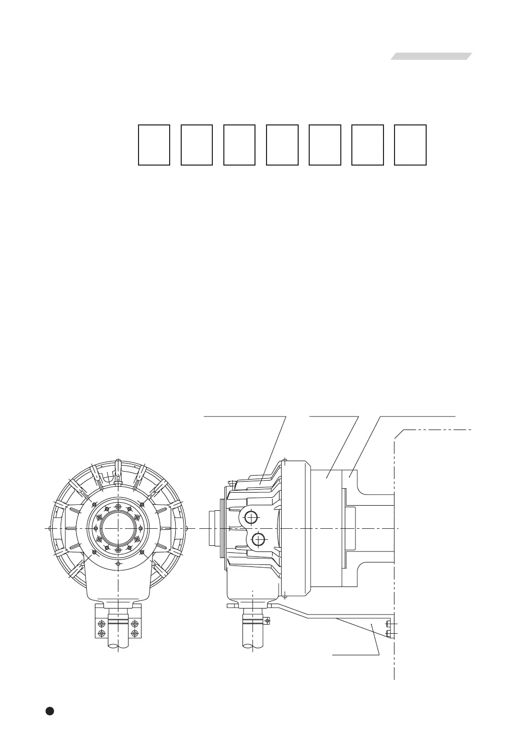
Structuraldrawing
Fig.1
S
1.StructuralDrawingandPartsList
・To prevent the work from flying, safe design, maintenance and erroneous action prevention of the hydraulic
system to maintain the gripping force of the chuck is extremely important. Thoroughly read the Important
SafetyPrecautionsonandafterpage6inthismanual.
・Asforthechuck,followtheinstructionmanualforthechuck.
1
Example
12
2
46
3 4 5 6 7
5thdigitandafterthatarenotdisplayedforthestandardcylinders.
1. S AbbreviatednameofScylinders
2. 12Nominalinsidediameterofthecylinder
3. 46Nominalthru-holediameter
4. −Cylinderwithlockvalve,reliefvalveandfan(Standardspecification)
L Longstroketypecylinderwithlockvalve,reliefvalveandfan
5〜7 Columnsforspecialspecificationforeachdestinationofdelivery
Remarks1)Whatisalockvalve?
Thisisavalvewhichhasafunctiontoretainthehydraulicpressureinsideacylindertemporarily
whenthepumppressuresuddenlylowersasaresultofblackout,malfunctionofthehydraulic
pump,etc.
Remarks2)Whatisareliefvalve?
Thisisavalvewhichhasafunctiontostopdamagewhenthehydraulicoilfilledinsidethe
cylinderhasincreaseditspressureduetothevolumechange.