~
IMPORTANT
READ BEFORE INSTALLING TO SAVE TIME, WORK, ASSURE PROPER
PERFORMANCE, AND OWNER’S WARRANTY PROTECTION.
ELECTRICAL SPECIFICATION:
Wiring must conform to National Electrical Code,
(N.E.C.), NFPA 970, 1981 and/or all applicable
Voltage & Frequency . . . . . . .
115 volts, 60 hertz
local electrical codes.
Operating load . . . . . . . . . . . 9 amperes, 695 watts
Circuit Fuse . . . . . . . . . . . . . . . . . . . . 15 amperes
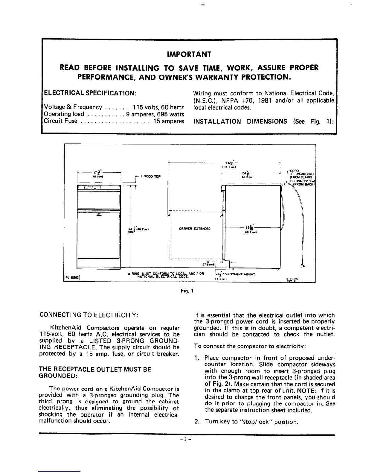
INSTALLATION DIMENSIONS (See Fig. 1):
DRAWER EXTEWD
WIRING
MUST CONFORM TO LOCAL AN
NATIONAL ELECTRICAL CODE.
TMENT HEIGHT
“I;:” ‘9
Fig. 1
CONNECTING TO ELECTRICITY:
KitchenAid Compactors operate on regular
1 15-volt, 60 hertz A.C. electrical services to be
supplied by a LISTED 3-PRONG GROUND-
ING RECEPTACLE. The supply circuit should be
protected by a 15 amp. fuse, or circuit breaker.
It is essential that the electrical outlet into which
the 3-pronged power cord is inserted be properly
grounded. If this is in doubt, a competent electri-
cian should be contacted to check the outlet.
To connect the compactor to electricity:
1.
Place compactor in front of proposed under-
counter location. Slide compactor sideways
with enough room to insert 3-pronged plug
into the 3-prong wall receptacle (in shaded area
of Fig. 2). Make certain that the cord is secured
in the clamp at top rear of unit. NOTE: If it is
desired to change the front panels, you should
do it prior to plugging the compactor in. See
the separate instruction sheet included.
THE RECEPTACLE OUTLET MUST BE
GROUNDED:
The power cord on a KitchenAid Compactor is
provided with a 3-pronged grounding plug. The
third prong is designed to ground the cabinet
electrically, thus eliminating the possibility of
shocking the operator if an internal electrical
malfunction should occur.
2. Turn key to “stop/lock” position.
-2-
 Loading...