Direct wire method: Copper or AJuminum wire
NOTE:The bag containing three
aiuminum terminai Hugs must be used
when making a direct wire connection.
Emectrica[ Shock Hazard
Disconnect power before servicing.
Use 8 gauge copper wire, or 6 gauge
aluminum wire.
Electrically ground range.
Failure to follow these instructions can
result in death, fire, or electrical shock.
This range may be connected directiyto
the fuse disconnect or circuitbreaker box;
or with a U+L+-Hsted, 40 amp range power
suppiy came+ Depending on your
eiectrisa[suppiy, make the required
three-wire or four-wire connection+
1. Disconnect power.
2. Remove the knockout as needed for
conduit connection.
Assemble a
U.L,-listed
conduit
connector in
opening+
4. Strip outer covering back 3 inches to
expose wires. Strip the insulation back
1 inch from the end of each wire.
I
5.
6.
Allow enough slack in the wire to
easily attach the wiring terminal
block.
Use 3/8" nut driver and remove the
outside nuts on the terminal block
screws+ Do not loosen the factory-
tightened nuts behind the outside
nuts+
__terminal
[ _ set screw
[ must face out
X IMPORTANT: the aluminum terminal
lugs must be assembled to the
terminal posts with the set screws
facing out as shown+
8+ Attach three aluminum terminal lugs
to terminal posts+
Use a 3/8" nut driver and tighten the
nuts securely+ Nuts must be
tightened to 20 in/Ibs of torque for
proper electrical connection.
9+ Complete electrical connection
according to your type electrical
supply ("Four-wire electrical
connection" or "Three+wire electrical
connection[')
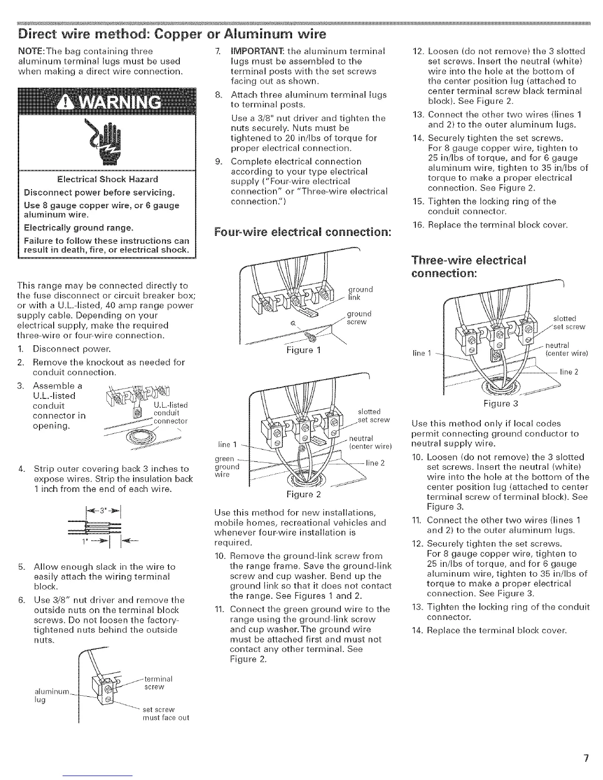
Figure 1
lineI
green_
ground
wire
_ted
+en,erw,re>
Figure 2
Use this method for new installations,
mobile homes, recreational vehicles and
whenever four-wire installation is
required.
10+ Remove the ground-link screw from
the range frame. Save the ground-link
screw and cup washer+ Bend up the
ground link so that it does not contact
the range. See Figures 1 and 2+
11. Connect the green ground wire to the
range using the ground-link screw
and cup washer.The ground wire
must be attached first and must not
contact any other terminal See
Figure 2+
15.
16+
12. Loosen (do not remove) the 3 slotted
set screws+ insert the neutral (white)
wire into the hole at the Bottom of
the center position lug (attached to
center terminal screw black terminal
block)+ See Figure 2.
13. Connect the other two wires dines 1
and 2) to the outer aluminum lugs.
14. Securely tighten the set screws.
For 8 gauge copper wire, tighten to
25 in/Ibs of torque, and for 6 gauge
aluminum wire, tighten to 35 in/Ibs of
torque to make a proper electrical
connection+ See Figure 2.
Tighten the locking ring of the
conduit connector.
Replace the terminal block cover+
Three-wire electdea[
connection:
_tted
_;_?_ set screw
_ _ @j 'qT_ neutral
Figure 3
Use this method only if local codes
permit connecting ground conductor to
neutral supply wire+
10+ Loosen (do not remove) the 3 slotted
set screws+ Insert the neutral (white}
wire into the hole at the bottom of the
center position lug (attached to center
terminal screw of terminal block). See
Figure 3+
11. Connect the other two wires dines 1
and 2) to the outer aluminum lugs+
12+ Securely tighten the set screws.
For 8 gauge copper wire, tighten to
25 in/ibs of torque, and for 6 gauge
aluminum wire, tighten to 35 in/Ibs of
torque to make a proper electrical
connection+ See Figure 3+
13+ Tighten the locking ring of the conduit
connector+
14. Replace the terminal block cover.
 Loading...