! 0!1i.
,iezing of the
!Jressure reguiator is 6 in. water column (W C.) for natural gas and 10 in. W.C. for LP
gas
In order to check pressure regulator, the
inlet test pressure must be at least one (1”) W.C. gretaer than
setlrrig (7” for natural and 11” for LP). Maximum pressure to regulator must not exceed 14” W.C.
.f t.*ead sealant resistarit to natural and i.P gases is to be used on all threaded gas connections.
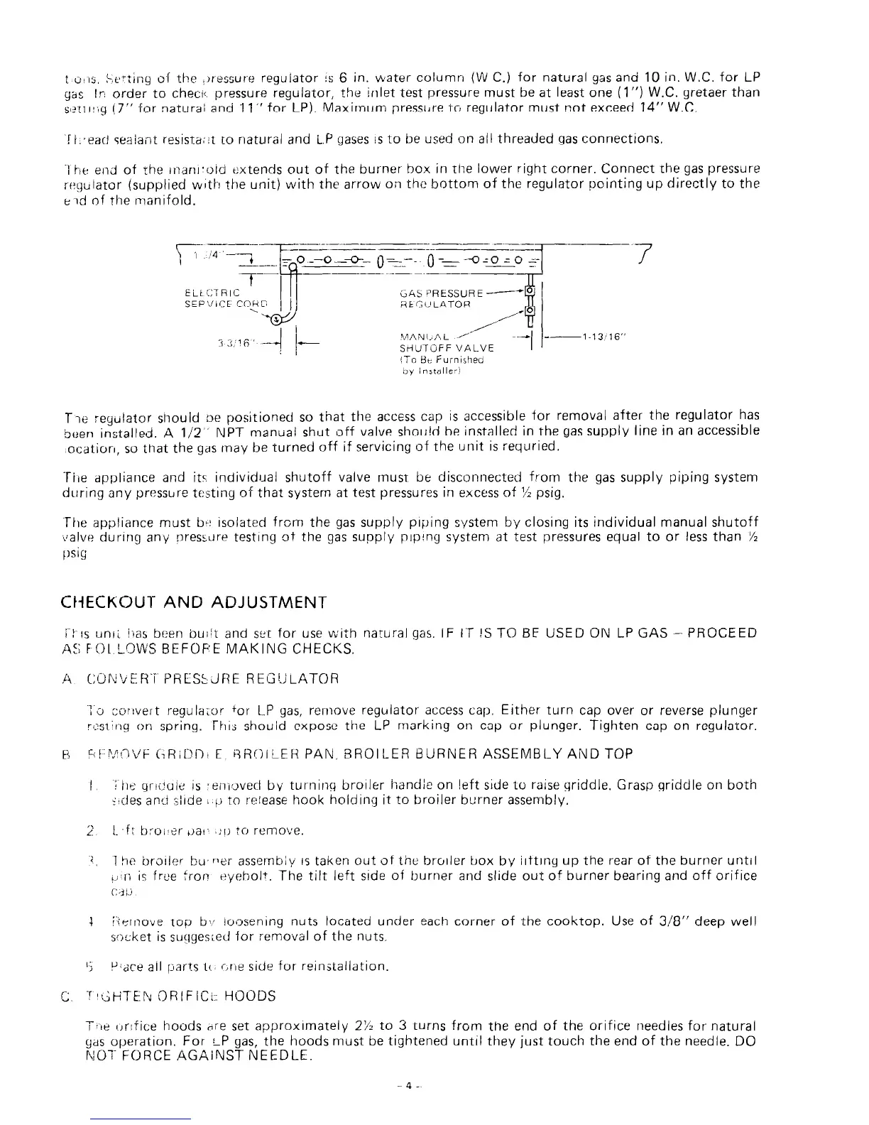
-1 he end of the rnanr’oid extends out of the burner box in the lower right corner. Connect the gas pressure
reiguiator (supplied vvlttr the unit) with the arrow on the bottom of the regulator pointing up directly to the
e Ed of the manifold.
G&S PRESSURE I-----
F?tG!?LATOR
:j 3,’ 1 fi --
-I i
*--l-:3/16"
)_
’ I
SilUTOFF VALVE
iTo Be F urnirhed
bv Installer;
Tie regulator should oe positioned so that the access cap is accessible for removal after the regulator has
been installed. A l/2 ’ NPT manual shut off valve shou!d be installed in the gas supply line in an accessible
ocatiorf, so that the gas may be turned off if servicing of the unit is requried.
‘Tire appliance and its individclal shutoff valve must be disconnected from the gas supply piping system
drlring any pressure testing of tha? system at test pressures in excess of % psig.
The appliance must bl-! isolated from the gas supply piping system by closing its individual manual shutoff
valve during any nressure testing of the gas supply plping system at test pressures equal to or less than 1/Z
psig
CHECKOUT AND ADJUSTMENT
1.i-rs unli iias been built and st’t for use with natural gas. IF 1.T !S TO BE USED ON LP GAS - PROCEED
AS F C>L LOWS BEFOF’E MAKING CHECKS,
.TV?
i i) :;or!vert regula;or
for L.P gas, remove regulator access cap. Either turn cap over or reverse plunger
rzstirlg on spring. This: should expose the LP marking on cap or plunger. Tighten cap on regulator.
et
F;!-:“$!?VE GRID& E, SHC>iiEH PAN, BROILER BURNER ASSEMBLY AND TOP
I 1 he gr!duld is *eni,Jvecl by turning broiler handle on left side to raise griddle. Grasp griddle on both
+des an:] ;lrde ,.:J to release hook holding it to broiler burner assembly.
1
1 he broiler buner assernbiy is taken out of the broiler box by iiftrng up the rear of the burner until
+n is free fron eyebolt. The tilt left srde of burner and slide out of burner bearing and off orifice
c 4 r.2
J Iiernove top b\, loosening nuts located under each corner of the cooktop. Use of 3/8” deep well
socket is suqges;ed for removal of the nuts.
1;
P’dce all parts ti.. c;r~e side for reinstallation.
P,re
IJrifice
hoods tire set approxrmately 2% to 3 turns from the end of the orifice needles for natural
gas operation. For LP gas, the hoods must be tightened until they just touch the end of the needle. DO
NOT FORCE AGAiNST NEEDLE.
4-



 To Next Page