EasyManua.ls Logo

Kitronik 2143K - User Manual

Kitronik 2143K
30 pages
Print Icon
To Next Page IconTo Next Page
Loading...
HIGH POWER AMPLIFIER KIT
PLAY IT LOUD AND PLAY IT PROUD WITH THIS
TEACHING RESOURCES
SCHEMES OF WORK
DEVELOPING A SPECIFICATION
COMPONENT FACTSHEETS
HOW TO SOLDER GUIDE
Version 2.
0
Question and Answer IconNeed help?

Do you have a question about the Kitronik 2143K and is the answer not in the manual?

Summary

Teaching Resources

Introduction

Overview of the project kit and its use in KS3 Design and Technology lessons.

Schemes of Work

Outlines two schemes for teaching the amplifier kit, including full project and electronics-only options.

Answers

Provides answers to technical questions on resistor and capacitor values for practical exercises.

The Design Process

Explains the structured steps involved in designing and developing a product, from brief to improvement.

Soldering in Ten Steps

A step-by-step guide to soldering electronic components onto a PCB, with visual aids and joint examples.

Resistor Values

Explains how to identify resistor values using colour bands and calculating markings, including tolerance.

LEDs & Current Limit Resistors

Details the function of LEDs, current limit resistors, and Ohm's Law for calculating necessary resistance values.

Capacitor Basics

Explains what capacitors are, how they charge and discharge, and the importance of maximum working voltage.

Ceramic Disc Capacitors

Covers how to read values from ceramic disc capacitors using the common 3-digit code system.

Instruction Manual

Guides on identifying key points to include when writing assembly instructions for the amplifier kit.

Evaluation

Provides methods for evaluating a completed design against specifications and identifying areas for improvement.

Packaging Design

Outlines requirements for product packaging for retail and prompts for developing a design concept.

Essential Information

Build Instructions

Step-by-step guide for assembling the High Power Amplifier kit components onto the PCB.

Checking Your Amplifier PCB

Provides a checklist for verifying correct component placement and soldering before powering up the amplifier.

Fault finding flow chart

A visual guide to diagnose and resolve common issues encountered with the amplifier kit's functionality.

Designing the Enclosure

Considers key factors and provides technical drawings for designing a suitable enclosure for the amplifier.

How the Amplifier Works

Explains the circuit diagram and the function of each major component in the High Power Amplifier.

Online Information

Provides links to download additional resources and contact details for technical support and sales.

Overview

This document describes the Kitronik High Power Amplifier Kit, a project kit designed for educational use, particularly in KS3 Design and Technology lessons. It serves as both a teaching resource and a build instruction manual for constructing a stereo amplifier.

Function Description

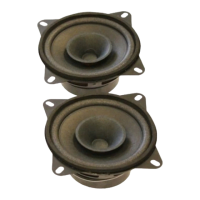
The Kitronik High Power Amplifier Kit allows users to build a functional stereo amplifier. Its primary function is to amplify audio signals, enabling connection to speakers for sound output. The kit includes a Printed Circuit Board (PCB), various electronic components, speakers, and necessary wiring. It's designed to introduce students to electronics and electronic construction, covering aspects from design and soldering to fault finding and evaluation. The amplifier circuit is relatively simple, with the core amplification handled by an integrated circuit (IC), the TDA7297. It takes an audio input, amplifies both the voltage and current, and drives two speakers. A power switch controls the circuit, and an LED indicates power status. A dual potentiometer acts as a volume control.

Important Technical Specifications

  • Amplifier IC: TDA7297
  • Power Input: Up to 20V (DC Jack connection). The kit's supplied power supply instantly cuts power if connected incorrectly to protect the IC.
  • Resistors: Includes 47KΩ (R1, R2), 1KΩ (R3).
  • Capacitors:
    • Electrolytic: 10µF (C4), 470µF (C1)
    • Ceramic Disc: 100nF (C2, marked 104), 220nF (C3, C5)
  • Diode: D1 (for reverse polarity protection)
  • LED: LED1 (power indicator)
  • Potentiometer: Dual 10K pot (R4, for volume control)
  • Speakers: Two speakers are included, with '+' and '-' indicators for connection.
  • PCB Dimensions: 77.5mm (width) x 59mm (height, including components = 65mm).
  • Speaker Dimensions: 116.5mm diameter, 60mm depth. Mounting holes are 4.8x7.8mm.
  • Mounting: The PCB has four 3.3mm diameter mounting holes designed for M3 bolts, allowing it to be fixed to an enclosure using hex spacers.
  • Output: Stereo speaker output (OUT1, OUT2)
  • Input: Stereo Jack / iPod lead connection (INPUT)
  • Manufacturing: Designed and manufactured in the UK by Kitronik.

Usage Features

  • Educational Focus: The kit is primarily a teaching resource, offering a structured approach to learning electronics and product design. It includes schemes of work, design briefs, investigation prompts, specification development, and evaluation sheets.
  • Build Instructions: Detailed, step-by-step instructions are provided for assembling the PCB, including component placement (smallest to tallest), soldering techniques, and connecting external components like speakers and power.
  • Soldering Guide: A "Soldering in Ten Steps" guide covers proper soldering techniques, including cleaning the iron, applying solder, and trimming leads. It also illustrates good vs. bad solder joints.
  • Component Identification: Information on identifying resistor values (color codes) and capacitor values (ceramic disc codes) is included, along with explanations of tolerance and preferred values.
  • Design Process Integration: The kit encourages a full product design cycle, from initial brief and research to design, prototyping (enclosure modeling), group design review, and final evaluation.
  • Fault Finding: A comprehensive fault-finding flow chart is provided to diagnose common issues, such as LED not lighting, no music heard, or one channel not working. This helps users troubleshoot their assembled circuit.
  • Enclosure Design: Technical drawings of the PCB and speakers are provided to aid in designing a custom enclosure, considering mounting, cable routing, and integration with an MP3 player.
  • Audio Input: The kit supports a standard stereo Jack / iPod lead for audio input.
  • Volume Control: A dual potentiometer allows for volume adjustment.

Maintenance Features

  • Troubleshooting Guide: The "Fault finding flow chart" is a key maintenance feature, guiding users through systematic checks to identify and rectify assembly errors or component issues.
  • PCB Checking: Before connecting power, users are instructed to perform thorough checks on the PCB, verifying that all holes are filled and soldered, no pins are shorted, components are correctly oriented (e.g., capacitors, LED, diode), and connections are in the right place with correct polarity.
  • Online Resources: Additional support and resources are available online at www.kitronik.co.uk/2143, including component fact sheets, information on calculating resistor and capacitor values, and puzzles.
  • Technical Support: Kitronik offers next-day response technical assistance via email (support@kitronik.co.uk) and phone (+44 (0) 845 8380781) for questions or suggestions.
  • Evaluation and Improvement: The manual includes sections for evaluating the final product against the specification and identifying areas for improvement, encouraging a continuous design cycle.

Kitronik 2143K Specifications

General IconGeneral
BrandKitronik
Model2143K
CategoryAmplifier
LanguageEnglish