FM Radio Essentials
www.kitronik.co.uk/2157
This is a very small metal cylinder with two very thin legs protruding from one end. Gently place this
component into the holes in the PCB where it is marked XTAL1. The legs are fragile so care should be taken
when putting them through the holes in the PCB.
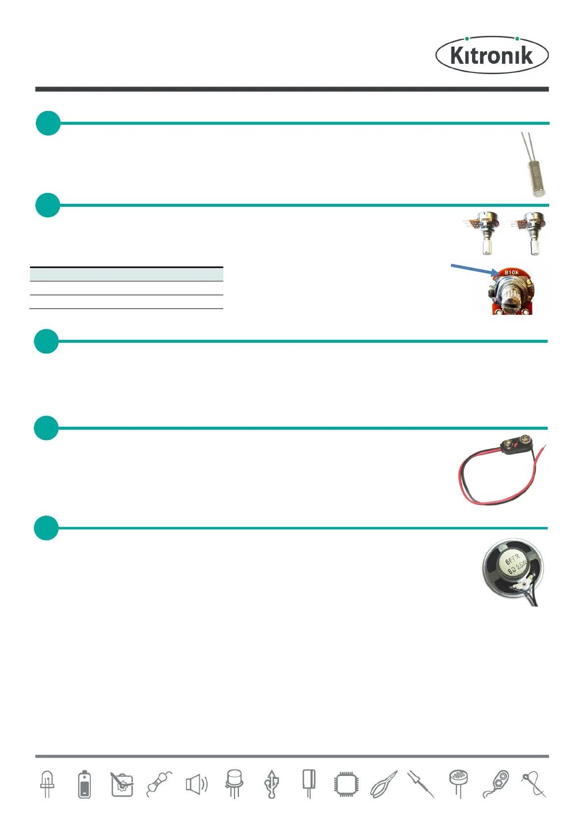
The two potentiometers are different so make sure that you check which is which
before soldering them into position. When placing the potentiometer into the board
make sure the knob is pointing outwards from the PCB.
Strip one end of the thin white wire and solder it into the hole on the PCB labelled Antenna. The longer the antenna
wire is up to 56cm the better it will perform. It is not a problem to have an antenna longer than 56cm as it wont
degrade the reception. Keep the off cut for the speaker.
Next look for the two holes labelled Power. Thread the wires from the PP3 clip through the
strain relief hole near these holes then solder the red wire into the hole marked red and the
black wire into the hole marked black.
Finally, cut the wire left over from the antenna connection in half and strip the ends. Thread both
lengths of wire through the strain relief hole marked Speaker and solder one of the wires to
each of the two holes, it doesnt matter which one goes in either hole.
Solder the other end of the speaker wires to the terminals on the speaker. Again it doesnt
matter which way around these go.
SOLDER THE TIMING CRYSTAL
SOLDER THE POTENTIOMETERS
 Loading...