FM Radio Essentials
www.kitronik.co.uk/2157
Build Instructions
Before you start, take a look at the Printed Circuit Board (PCB). The components go in the side with the writing on
and the solder goes on the side with the tracks and silver pads.
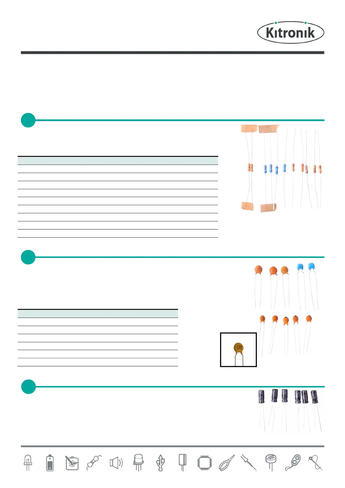
Start with the eleven resistors:
The text on the PCB shows where R1, R2 etc go.
Ensure that you put the resistors in the right place.
The ceramic disc capacitors should be soldered into the board. There are a lot of these
so be careful to put them all in the correct place. The capacitors can be identified by
the text printed on them (see close up image below right). To allow for easier soldering
wide footprints have been used on the board, the smaller capacitors do not need to be
pushed firmly in to the PCB.
The other six capacitors are electrolytic capacitors. The capacitor C10 is marked 100µF,
place this one first. Make sure that the device is the correct way around. The capacitors
have a ‘-’ sign marked on them, which should match the same sign on the PCB. The
other 5 are all marked 1µF and should go in the spaces marked C11, C12, C13, C15 and
C16.
SOLDER THE CERAMIC DISC CAPACITORS