D
GB
26
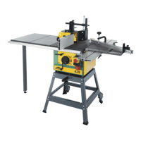
6. INBETRIEBNAHME DER MASCHINE
6. Montage des Stützfußes an der Schlittenschiene (13)
7. Montage des Spindelanschlags (14)
g. Montage des sonderzubehörs
5. Montage der Absaugeinheit (12)
- Stecken Sie das Schlauchende auf den Absaugstutzen der
Schutzvorrichtung.
- Ziehen Sie den Metallring (F) auf dem Schlauch mit Hilfe der
Schraube fest an.
6. PUTTING THE MACHINE INTO OPERATION
6. Fitting the supporting leg to the carriage rail (13)
7. Fitting the spindle fence (14)
g. Fitting the optional equipment
5. Fitting the suction unit (12)
- Schieben Sie den Fuß so unter die Schiene, dass die
2 Schraubenköpfe (G1) im Hohlraum des Profils an der
Grundmaschine laufen. (siehe Detail)
- Ziehen Sie die beiden Muttern fest an
- Platzieren Sie den Zapfen des Spindelanschlags in das Loch
im Maschinentisch, das zu diesem Zweck vorgesehen ist (H
1).
- Justieren Sie die Fixierschraube des Anschlags im Gewindeloch
des Tisches (H2).
- Fixieren Sie das Ganze und ziehen Sie die Rändelmutter (C2)
des Anschlags fest an.
- Put the hose end onto the suction connection of the guard.
- Firmly thighten the bolt of the metal ring (F) on the hose.
- Slide the leg underneath the rail in such a way that the 2 bolt
heads (G
1) run in the hollow space of the machine profile (see
detail)
- Firmly tighten both nuts.
- Place the tappet of the spindle fence in the table hole provi-
ded to this purpose (H
1).
- Adjust the fixing bolt of the fence in the threaded table hole
(H
2).
- Fix the whole by firmly tightening the knob (C2).