ENGLISH
CLEANING
Be sure tester is turned off and wipe with a clean, dry lint-free cloth.
Do not use
abrasive cleaners or solvents.
Be sure tester is turned off and wipe with a clean, dr
y lint-free cloth.
abrasive cleaners or solvents.
Be sure tester is turned off and wipe with a clean, dr
y lint-free cloth.
DISPOSAL / RECYCLE
Do not place equipment and its accessories in the trash. Items must be properly
disposed of in accordance with local regulations. Please see
Do not place equipment and its accessories in the trash. Items must be properly
disposed of in accordance with local regulations. Please see
Do not place equipment and its accessories in the trash. Items must be properly
epa.gov/recycle
Do not place equipment and its accessories in the trash. Items must be properly
Do not place equipment and its accessories in the trash. Items must be properly
for
Do not place equipment and its accessories in the trash. Items must be properly
Do not place equipment and its accessories in the trash. Items must be properly
additional information.
disposed of in accordance with local regulations. Please see
disposed of in accordance with local regulations. Please see
CLEANING
Be sure tester is turned off and wipe with a clean, dry lint-free cloth.
Do not use abrasive cleaners or solvents.
DISPOSAL / RECYCLE
Do not place equipment and its accessories in the trash. Items must be properly
disposed of in accordance with local regulations. Please see epa.gov/recycle for
additional information.
BATTERY REPLACEMENT
Should one of the following scenarios occur, the batteries must be replaced:
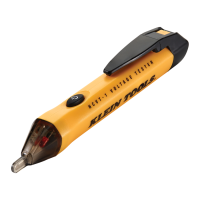
SCENARIO 1: When powering on the tester: The “power on” LED in the tip of the tester
changes from a steady green to a blinking green and a series of beeping sounds is generated,
the tester then turns off.
SCENARIO 2: When operating the tester: The LEDs dim and the tone fades.
To replace the batteries:
1. Press the locking tab
6
inward and remove the battery cap inward and remove the batter
y cap
5
.
2. Remove and recycle the two spent AAA batteries.
3. Install two new AAA batteries, with the positive (+) side facing into the tester as shown
7
.
4. Slide the battery cap onto the tester until it snaps back into place.
Presione la pestaña de cierre
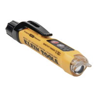
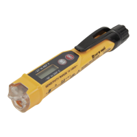
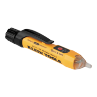
NCVT-1P (FIG. 1)
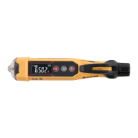
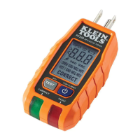
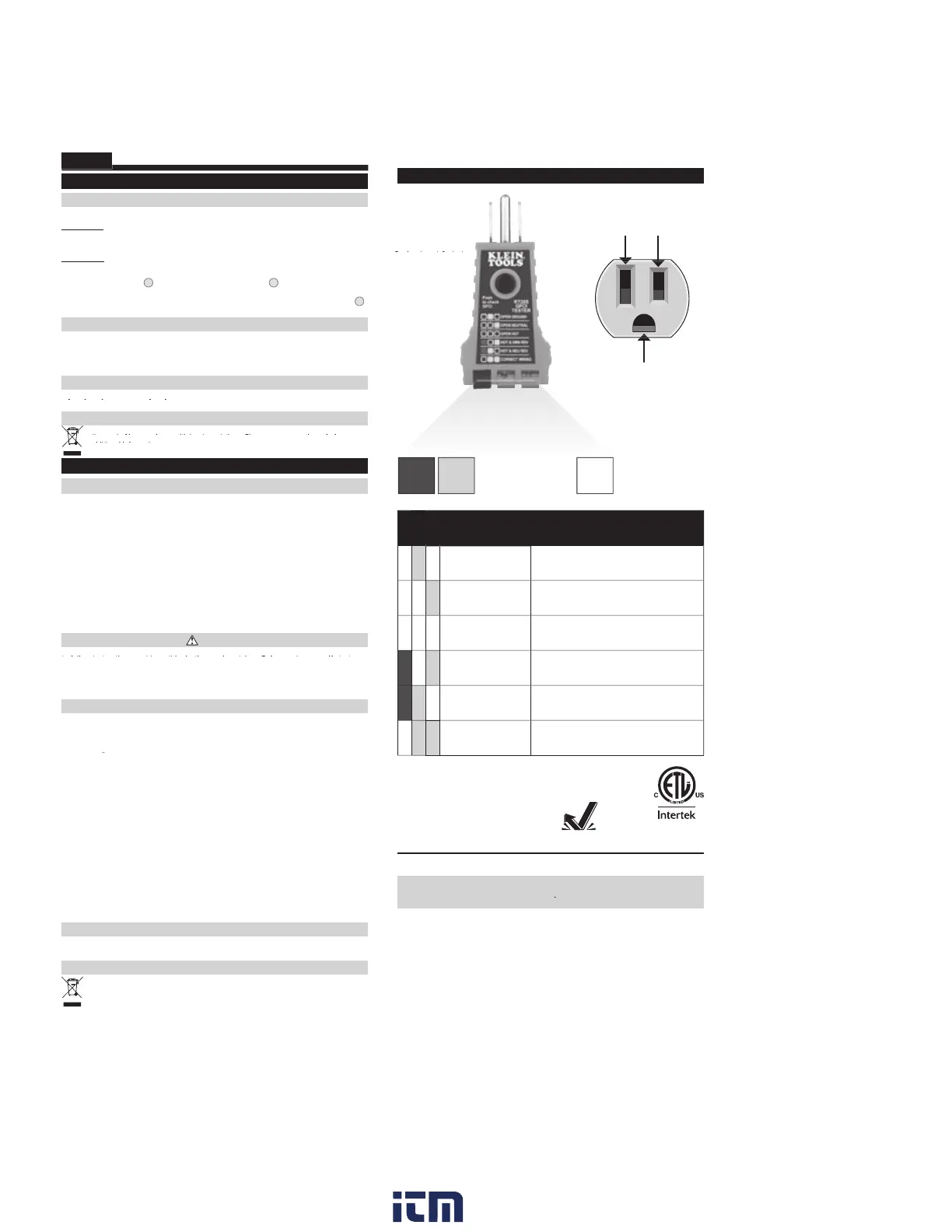
RT205 (FIG. 2)
STORAGE
Remove the batteries when not in use for a prolonged period of time. Do not expose to high
temperatures or humidity. After a period of storage in extreme conditions exceeding the
limits mentioned in the General Specifications section, allow the tester to return to normal
operating conditions before using.
GENERAL SPECIFICATIONS
The Klein Tools RT205 is a receptacle tester designed to detect the most common wiring
problems in standard receptacles.
Environment: Indoor. Do NOT expose to moisture rain or snow.
Operating Altitude: 6562 ft. (2000m)
Operating Temperature: 32° to 104°F (0°C to 40°C) < 80% R.H.
Storage Temperature: 14° to 122°F (-10°C to 50°C) < 70% R.H.
Weight: 1.5 oz. (43 g)
Nominal Voltage: 110-125V AC at 50/60Hz in 3-wire outlet
MAINS Supply Voltage Fluctuation: ± 10%
Nominal Power: 0.3W
Certi cation: Conforms to: UL61010-1, 61010-2-30. Certified to: CSA-C22.2 #61010-1, 61010-2-30
Pollution degree: 2
Safety: CAT II 125V, Class 2, Double Insulation
Drop Protection: 6.6 ft. (2 m)
WARNINGS
Read, understand, and follow all warnings and instructions before operating testers. Failure
to follow instructions could result in death or serious injury. Before each use, verify tester
Read, understand, and follow all warnings and instructions before operating testers. Failure
to follow instructions could result in death or serious injury. Before each use, verify tester
Read, understand, and follow all warnings and instructions before operating testers. Failure
operation by testing on a known live and correctly wired receptacle. Do not use if the tester
to follow instructions could result in death or serious injury. Before each use, verify tester
operation by testing on a known live and correctly wired receptacle. Do not use if the tester
to follow instructions could result in death or serious injury. Before each use, verify tester
appears damaged in any way. The tester is intended for indoor use only. Other equipment or
operation by testing on a known live and correctly wired receptacle. Do not use if the tester
appears damaged in any way. The tester is intended for indoor use only. Other equipment or
operation by testing on a known live and correctly wired receptacle. Do not use if the tester
devices attached to the circuit being tested could interfere with the tester. Clear the circuit
appears damaged in any way. The tester is intended for indoor use only. Other equipment or
devices attached to the circuit being tested could interfere with the tester. Clear the circuit
appears damaged in any way. The tester is intended for indoor use only. Other equipment or
before testing. Always consult a qualified electrician to resolve wiring problems.
devices attached to the circuit being tested could interfere with the tester. Clear the cir
cuit
before testing. Always consult a qualified electrician to resolve wiring problems.
devices attached to the circuit being tested could interfere with the tester. Clear the cir
cuit
WIRING CONFIGURATION TESTING
Conditions indicated: wiring correct, open ground, reverse polarity, open hot, open neutral and hot/ground reversed.
Conditions NOT indicated: quality of ground, multiple hot wires, combinations of defects, reversal of grounded
and grounding conductors.
quality of ground, multiple hot wires, combinations of defects, reversal of grounded
and grounding conductors.
quality of ground, multiple hot wires, combinations of defects, reversal of grounded
All appliances or equipment on the circuit being tested should be unplugged to help reduce the possibility of
erroneous readings.
All appliances or equipment on the cir
cuit being tested should be unplugged to help reduce the possibility of
All appliances or equipment on the cir
cuit being tested should be unplugged to help reduce the possibility of
STANDARD RECEPTACLES
1. Verify tester operation by testing on a known live and correctly wired receptacle.
2. Plug tester into receptacle.
3. Compare the illuminated lights on the tester to the key code printed on the tester.
4. If the tester indicates that the receptacle is not wired correctly, consult a qualified electrician.
GFCI RECEPTACLES
1. Check the GFCI receptacle user manual for information on how the specific receptacle operates prior to
using this tester.
Check the GFCI receptacle user manual for information on how the specific receptacle operates prior to
Check the GFCI receptacle user manual for information on how the specific receptacle operates prior to
2. Insert the tester into the receptacle under test to check for correct wiring. Lights on the tester should illuminate.
3. Press the “TEST” button on the GFCI receptacle.
Did the GFCI trip and the lights on the tester go dark?
YES:
Reset the GFCI by pressing the reset button. Proceed to step 4.
YES:
Reset the GFCI by pressing the reset button. Proceed to step 4.
YES:
NO:
The GFCI is not operating properly or the receptacle is miswired. Consult a qualified electrician.
NO:
The GFCI is not operating properly or the receptacle is miswired. Consult a qualified electrician.
NO:
4. Press and hold the test button on the tester for 7 seconds.
Did the GFCI trip and the lights on the tester
go dark?
YES:
Reset the GFCI by pressing the reset button. The GFCI appears to be operating properly.
YES:
Reset the GFCI by pressing the reset button. The GFCI appears to be operating properly.
YES:
NO:
The GFCI is not operating properly or the receptacle is miswired. Consult a qualified electrician.
NO:
The GFCI is not operating properly or the receptacle is miswired. Consult a qualified electrician.
NO:
FCC & IC COMPLIANCEFCC & IC COMPLIANCE
CONFORMIDAD CON LA NORMATIVA FCC/ICCONFORMIDAD CON LA NORMATIVA FCC/IC
CONFORMITÉ FCC ET IC
CONFORMIDAD CON LA NORMATIV
A FCC/IC
CONFORMIDAD CON LA NORMATIV
A FCC/IC
See this product’s page FCC compliance information.
FIG. 2 - RT205
cuito sometido a prueba para
ayudar a reducir la posibilidad de que se produzcan lecturas erróneas.
cuito sometido a prueba para
, lea el manual del usuario del receptáculo GFCI para obtener información sobre
su funcionamiento.
, lea el manual del usuario del receptáculo GFCI para obtener información sobre
che dans la pointe du testeur se met
à clignoter et une série de bips se fait entendre, puis le testeur s’éteint.
che dans la pointe du testeur se met
, puis retirez le couvercle du compartiment à piles
ools est conçu pour détecter les problèmes de câblage les plus
fréquents dans lesprises standard.
ools est conçu pour détecter les problèmes de câblage les plus
AS le produit à l’humidité, à la pluie ou à la neige.
Altitude de fonctionnement:
AS le produit à l’humidité, à la pluie ou à la neige.
T
-10°C à 50°C (14°F à 122°F) <70% H.R.
T
CATII125V
2m (6,6pi)
CATII125V
cuit vérifié doivent être
débranchés pour réduire le risque de lecture erronée.
cuit vérifié doivent être
4007177
Indicator IlluminatedRed Yellow
Indicator Not Illuminated
Indicator Fault Explanation
Open Ground
Ground contact is not connected
Open Neutral
Neutral contact is not connected
Open Hot
Hot contact is not connected
Hot/Ground Reversed
Hot and ground connections are reversed
Hot/Neutral Reversed
Hot and neutral connections are reversed
Correct
Receptacle is wired correctly
Hot (Black)Neutral (White)
Ground (Green)
2 m
CAT II
125V
w ww. . com
information@itm.com1.800.561.8187
 Loading...