probador cer
se encenderá.
probador cer
NON-CONTACT VOLTAGE AND GFCI RECEPTACLE TEST KIT
INSTRUCTIONS
1390617 Rev. 07/22 B
NCVT1PKIT
ENGLISH
CONTINUED ON OTHER SIDE
5000573
CAT IV
1000V
2 m
CAUTION
• DO NOT attempt to repair this tester. It contains no serviceable parts.DO NOT
attempt to repair this tester. It contains no serviceable parts.
DO NOT
• DO NOT expose tester to extremes in temperature or high humidity.DO NOT
expose tester to extremes in temperature or high humidity.
DO NOT
WARNINGS
To ensure safe operation and service of the tester, follow these instructions. Failure to observe
these warnings can result in severe injury or death.
To ensure safe operation and service of the tester, follow these instructions. Failure to obser
ve
these warnings can result in severe injury or death.
To ensure safe operation and service of the tester, follow these instructions. Failure to obser
ve
• It is important that users of this tester read, understand, and follow all warnings, cautions, safety information,
these warnings can result in severe injury or death.
It is important that users of this tester read, understand, and follow all warnings, cautions, safety information,
these warnings can result in severe injury or death.
and instructions in this manual before operating or servicing this tester. Failure to follow instructions could
It is important that users of this tester read, understand, and follow all warnings, cautions, safety information,
and instructions in this manual before operating or servicing this tester. Failure to follow instructions could
It is important that users of this tester read, understand, and follow all warnings, cautions, safety information,
result in death or serious injury.
and instructions in this manual before operating or ser
vicing this tester. Failure to follow instructions could
result in death or serious injury.
and instructions in this manual before operating or ser
vicing this tester. Failure to follow instructions could
• Risk of electric shock and burn. Contact with live circuits could result in death or serious injury.
result in death or serious injury.
Risk of electric shock and burn. Contact with live circuits could result in death or serious injury.
result in death or serious injury.
• Use caution with voltages above 30V AC as a shock hazard may exist.
Risk of electric shock and burn. Contact with live circuits could result in death or serious injur
y.
Use caution with voltages above 30V AC as a shock hazard may exist.
Risk of electric shock and burn. Contact with live circuits could result in death or serious injur
y.
• A blinking or steady red glow and an audible beep indicate voltage present. If no indication, voltage could
Use caution with voltages above 30V AC as a shock hazard may exist.
A blinking or steady red glow and an audible beep indicate voltage present. If no indication, voltage could
Use caution with voltages above 30V AC as a shock hazard may exist.
still be present.
A blinking or steady red glow and an audible beep indicate voltage present. If no indication, voltage could
A blinking or steady red glow and an audible beep indicate voltage present. If no indication, voltage could
• Before and after each use, verify operation by testing a known working circuit that is within the rating of
still be present.
Before and after each use, verify operation by testing a known working circuit that is within the rating of
still be present.
this unit.
Before and after each use, verify operation by testing a known working cir
cuit that is within the rating of
Before and after each use, verify operation by testing a known working cir
cuit that is within the rating of
• Never assume neutral or ground wires are de-energized. Neutrals in multi-wire branch circuits may be
energized when disconnected and must be retested before handling.
Never assume neutral or ground wires are de-energized. Neutrals in multi-wire branch cir
cuits may be
energized when disconnected and must be retested before handling.
Never assume neutral or ground wires are de-energized. Neutrals in multi-wire branch cir
cuits may be
• The tester
energized when disconnected and must be retested before handling.
energized when disconnected and must be retested before handling.
WILL NOT
energized when disconnected and must be retested before handling.
energized when disconnected and must be retested before handling.
detect voltage if:
energized when disconnected and must be retested before handling.
energized when disconnected and must be retested before handling.
• The wire is shielded.
detect voltage if:
detect voltage if:
• The operator is not grounded or is otherwise isolated from an effective earth ground.
• The voltage is DC.
The operator is not grounded or is other
wise isolated from an effective earth ground.
The operator is not grounded or is other
wise isolated from an effective earth ground.
• The tester
The voltage is DC.
The voltage is DC.
MAY NOT
The voltage is DC.
The voltage is DC.
detect voltage if:
The voltage is DC.
The voltage is DC.
• The user is not holding the tester.
detect voltage if:
The user is not holding the tester.
detect voltage if:
• The user is insulated from the tester with a glove or other materials.
The user is not holding the tester.
The user is insulated from the tester with a glove or other materials.
The user is not holding the tester.
• The wire is partially buried or in a grounded metal conduit.
The user is insulated from the tester with a glove or other materials.
The wire is partially buried or in a grounded metal conduit.
The user is insulated from the tester with a glove or other materials.
• The tester is at a distance from the voltage source.
The wire is partially buried or in a grounded metal conduit.
The tester is at a distance from the voltage source.
The wire is partially buried or in a grounded metal conduit.
• The field created by the voltage source is blocked, dampened, or otherwise interfered with.
The tester is at a distance from the voltage source.
The field created by the voltage source is blocked, dampened, or otherwise interfered with.
The tester is at a distance from the voltage source.
• The frequency of the voltage is not a perfect sine wave between 50 and 500Hz.
The field created by the voltage source is blocked, dampened, or otherwise interfered with.
The frequency of the voltage is not a perfect sine wave between 50 and 500Hz.
The field created by the voltage source is blocked, dampened, or otherwise interfered with.
• The tester is outside of operation conditions (listed in Specifications section).
The frequency of the voltage is not a perfect sine wave between 50 and 500Hz.
The tester is outside of operation conditions (listed in Specifications section).
The frequency of the voltage is not a perfect sine wave between 50 and 500Hz.
• Operation may be affected by differences in socket design and insulation thickness and type; tester may not be
The tester is outside of operation conditions (listed in Specifications section).
Operation may be affected by differences in socket design and insulation thickness and type; tester may not be
The tester is outside of operation conditions (listed in Specifications section).
compatible with some types of standard or tamper resistant (TR) electrical outlets.
Operation may be affected by differences in socket design and insulation thickness and type; tester may not be
compatible with some types of standard or tamper resistant (TR) electrical outlets.
Operation may be affected by differences in socket design and insulation thickness and type; tester may not be
• In bright light conditions, the LED visual indicators will be less visible.
compatible with some types of standard or tamper resistant (TR) electrical outlets.
In bright light conditions, the LED visual indicators will be less visible.
compatible with some types of standard or tamper resistant (TR) electrical outlets.
• Do not use if “power on” LED is not illuminated.
In bright light conditions, the LED visual indicators will be less visible.
Do not use if “power on” LED is not illuminated.
In bright light conditions, the LED visual indicators will be less visible.
• Do not use if tester appears damaged or if the tester is not operating properly. If in doubt, replace the tester.
Do not use if “power on” LED is not illuminated.
Do not use if tester appears damaged or if the tester is not operating properly. If in doubt, replace the tester.
Do not use if “power on” LED is not illuminated.
• Do not apply more than the rated voltage as marked on the tester (1000 volts AC).
Do not use if tester appears damaged or if the tester is not operating properly. If in doubt, replace the tester
.
Do not apply more than the rated voltage as marked on the tester (1000 volts AC).
Do not use if tester appears damaged or if the tester is not operating properly. If in doubt, replace the tester
.
• Do not apply to uninsulated hazardous live conductors.
Do not apply more than the rated voltage as marked on the tester (1000 volts AC).
Do not apply to uninsulated hazardous live conductors.
Do not apply more than the rated voltage as marked on the tester (1000 volts AC).
• Detection above 50V is specified under “normal” conditions as specified below. The tester may detect at a
Do not apply to uninsulated hazardous live conductors.
Detection above 50V is specified under “normal” conditions as specified below. The tester may detect at a
Do not apply to uninsulated hazardous live conductors.
different threshold at different conditions, or may not detect at all unless:
Detection above 50V is specified under “normal” conditions as specified below
. The tester may detect at a
different threshold at different conditions, or may not detect at all unless:
Detection above 50V is specified under “normal” conditions as specified below
. The tester may detect at a
• The tip of the tester is within 0.25" of an AC voltage source radiating unimpeded.
different threshold at different conditions, or may not detect at all unless:
The tip of the tester is within 0.25" of an AC voltage source radiating unimpeded.
different threshold at different conditions, or may not detect at all unless:
• The user is holding the body of the tester with his or her bare hand.
The tip of the tester is within 0.25" of an AC voltage source radiating unimpeded.
The user is holding the body of the tester with his or her bare hand.
The tip of the tester is within 0.25" of an AC voltage source radiating unimpeded.
• The user is standing on or connected to earth ground.
The user is holding the body of the tester with his or her bare hand.
The user is standing on or connected to earth ground.
The user is holding the body of the tester with his or her bare hand.
• The air humidity is nominal (50% relative humidity).
The user is standing on or connected to earth ground.
The air humidity is nominal (50% relative humidity).
The user is standing on or connected to earth ground.
• The tester is held still.
The air humidity is nominal (50% relative humidity).
The tester is held still.
The air humidity is nominal (50% relative humidity).
• Always wear approved eye protection.
• Comply with local and national safety requirements.
Always wear approved eye protection.
Comply with local and national safety requirements.
Always wear approved eye protection.
• If this product is used in a manner not specified by the manufacturer, protection provided by the product
Comply with local and national safety requirements.
If this product is used in a manner not specified by the manufacturer, protection provided by the product
Comply with local and national safety requirements.
may be affected.
If this product is used in a manner not specified by the manufacturer
, protection provided by the product
If this product is used in a manner not specified by the manufacturer
, protection provided by the product
GENERAL SPECIFICATIONS
• Test
er Type: Non-contact voltage detector
• Voltage Range: 50 – 1000V AC
• Frequency Range: 50 – 500Hz
• Operating Altitude: 2,000 meters (6,561 feet)
• Relative Humidity: < RH 80% non-condensing
• Operating Temperature: 32 to 104°F (0° to 40°C)
• Storage Temperature: 32 to 104°F (0° to 40°C)
• Power: 2 x 1.5V AAA batteries (included)
• Dimensions: 6" x 0.96" x 1.16" x (152 x 24 x 29 mm)
• Weight: 2.5 oz. (72 grams)
• Drop Protection: 6.6 ft. (2 m)
• Safety Rating: CAT IV 1000V
• Pollution Degree: 2
• Standards: Conforms to UL STD. 61010-1, 61010-2-030
Certi ed to CSA STD. C22.2 No. 61010-1, 61010-2-030.
Specifications subject to change.
cuito activo que se
encuentre dentro de la capacidad de esta unidad.
cuito activo que se
.
No aplique voltaje nominal mayor que el indicado en el probador (1000V CA).
.
cionada
por el producto puede verse afectada.
cionada
T
2baterías AAA de 1,5V (incluidas)
T
appuyez sur
le bouton de mise en marche
appuyez sur
appuyez sur
et maintenez-le enfoncé jusqu’à ce que la DEL verte
appuyez sur
A
près d’une source de tension c.a. Dès la détection d’une tension de 50 à 1000V, le testeur produira un bip
A
ce de tension c.a. Dès la détection d’une tension de 50 à 1000V, le testeur produira un bip
, le testeur produira un bip
aigu et continu, puis la DEL rouge
, le testeur produira un bip
près d’une sour , le testeur produira un bip
s’allumera.
près d’une sour , le testeur produira un bip
. Il ne contient aucune pièce pouvant être réparée.
N’exposez PAS
. Il ne contient aucune pièce pouvant être réparée.
out contact avec un circuit sous tension peut provoquer des blessures
graves, voire la mort.
out contact avec un circuit sous tension peut provoquer des blessures
cuit dontvous connaissez l’état
de fonctionnement se trouvant à proximité de l’unité.
cuit dontvous connaissez l’état
r.
Évitez d’appliquer une tension supérieure à la tension nominale indiquée sur le testeur (1000V c.a.).
r.
, lorsque les conditions
sont différentes, à moins que:
, lorsque les conditions
T
0°C à 40°C (32°F à 104°F)
T
T
2piles alcalines AAA de 1,5V (comprises)
T
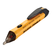
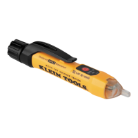
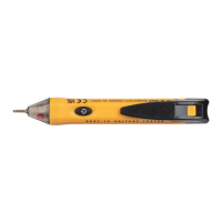
NCVT-1P (FIG. 1)
FIG. 1 - NCVT-1P
SYMBOLS ON TESTER
Risk of danger. Important information: It is important that users of this tester read,
understand, and follow all warnings, cautions, safety information, and instructions in this
Risk of danger.
understand, and follow all warnings, cautions, safety information, and instructions in this
Risk of danger. Important information:
understand, and follow all warnings, cautions, safety information, and instructions in this
Important information: It is important that users of this tester read,
understand, and follow all warnings, cautions, safety information, and instructions in this
It is important that users of this tester read,
manual before operating or servicing this tester. Failure to follow instructions could result
understand, and follow all warnings, cautions, safety information, and instructions in this
manual before operating or servicing this tester. Failure to follow instructions could result
understand, and follow all warnings, cautions, safety information, and instructions in this
in death or serious injury.
manual before operating or ser
vicing this tester. Failure to follow instructions could result
in death or serious injury.
manual before operating or ser
vicing this tester. Failure to follow instructions could result
Risk of
electric
shock
Read
instructions
Double
insulated
CAT
IV
For measurements performed
at the source of low-voltage
For measurements performed
at the source of low-voltage
For measurements performed
installation and outside lines.
at the source of low-voltage
installation and outside lines.
at the source of low-voltage
OPERATING INSTRUCTIONS
TURN UNIT ON:
Press and hold the power button
4
for ½ second, then release.
Listen for
single-beep sound and watch for the green LED
2
to
illuminate.
TURN UNIT OFF:
Press and hold the power button
4
for ½ second. Listen for a double-
beep sound and watch for the “power on” green LED
2
to
turn off.
SILENT MODE:
The tester can be operated with only visual indication of voltage. With the
tester powered off, press and hold the power button
4
until the green LED
2
illuminates,
then release.
SYSTEM SELF-TEST:
The “power on” green LED
2
visually confirms battery sufficiency,
system integrity, and operation/active mode.
CHECKING FOR THE PRESENCE OF AC VOLTAGE: Prior to use, test on known live circuit to verify
tester functionality. Place tip
1
of the tester near an AC voltage source. When 50V to 1000V voltage of the tester near an AC voltage sour
ce. When 50V to 1000V voltage
is detected, the tester will emit a high-pitched continuous beep, and the red LED
2
will illuminate.
AUTO POWER-OFF:
After 4 minutes of non-use, the tester automatically powers off to
conserve battery life.
ENGLISH
1.
Tip
2.
LEDs
3.
Tester body
4.
Power button
5.
Battery cap
6.
Locking tab
7.
2x AAA batteries (included)
NOTE: There are no user-
serviceable parts inside
tester.
serviceable parts inside
serviceable parts inside
1
6
4
3
2
5
7
w ww. . com
information@itm.com1.800.561.8187