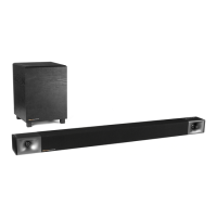
Please refer to the following drawings for installation details: Figures
17, 18, 19 and 20.
The bolt locations shown in "A" on Fig. 17 are common to models
KPT-250, KPT-200 and KPT-100 surround sound speakers, and are
used when mounting the speakers using a Goldberg bracket. The bolt
hole locations shown at "B" in Fig. 17 are used when mounting the
speakers using either an APC or OmniMount bracket.
Figure 21 shows the basic dimensions for the KPT-110. Location "A"
bolts and washers are to be used when mounting the speaker with a
Goldberg bracket.
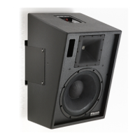
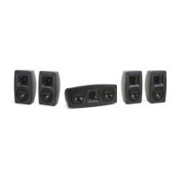
Installation drawings for the surround sound speaker systems are
located in the following section. All of the systems are pre-assembled
for installation on-site, and include passive frequency dividing
networks. Please refer to the specification page for power and
impedance information.
Connections to the internal passive frequency dividing networks are
made on the termination panel located in the top of the units. Note
that models KPT-200 and KPT-100 include internal SMPTE/ISO 2696
X-curve de-emphasis.
Klipsch surround speaker mounting hardware is designed for readily
available Goldberg, APC and OmniMount brackets.
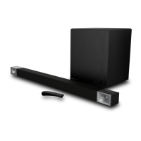
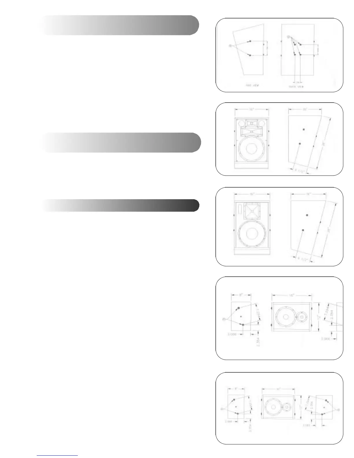
Mechanical Installation Drawings for KPT-250,
KPT-200 and KPT-100 Surround Sound Speakers
Mechanical Installation Drawing for KPT-110
Surround Sound Speaker
Surround Sound System Installation
Fig. 17
Fig. 18
Fig. 19
Fig. 20
Fig. 21
 Loading...