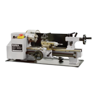
The Klutch Mini Metal Lathe 7 x 12 (Item# 49656) is a compact, light-duty, multi-purpose machine designed for typical turning processes to economically produce small precision parts, threaded parts, fittings, and dies. It features a low and high spindle speed, a change gear set, a wrench set, and an oil can.
Technical Specifications:
- Max. swing over bed: 7-1/16" (180mm)
- Distance between centers (Max. length of workpiece): 11-7/8" (300mm)
- Hole through spindle: 3/4" (20mm)
- Spindle hole taper: MT#3
- Tailstock taper: MT#2
- Cross slide travel: 2-1/2" (65mm)
- Compound travel: 2-3/16" (55mm)
- Range of threads - Metric version: 0.5-1.25mm (5 thread pitches)
- Imperial version: 16-24TPI (5 thread pitches)
- Spindle speed - Low range: 100-1100RPM
- Spindle speed - High range: 100-2500 RPM
- Motor: 3/4 HP
- Dimensions: 27-1/2 x 11-7/8 x 11-7/8
- Shipping Weight: 88 lbs.
Usage Features:
The manual emphasizes reading and understanding all instructions before operation to prevent serious injury or property damage. Users should exercise common sense and caution, ensuring the tool is used in a safe and responsible manner. Modifications to the product are not recommended as they may impair function and safety. The lathe is designed for specific applications, and forcing it to do the work of larger industrial equipment is discouraged. OSHA requirements must be followed for industrial or commercial applications.
Work Area Safety:
The work area must be clean, dry, free of clutter, and well-lit. The lathe should not be used in the presence of flammable liquids, gases, or dust due to the risk of sparks. Contact with electrical sources should be avoided as the tool is not insulated. Children and bystanders must be kept away from the work area. Users should be aware of power lines, electrical circuits, water pipes, and other mechanical hazards.
Personal Safety:
Operators must stay alert, watch what they are doing, and use common sense. The tool should not be used when tired or under the influence of drugs, alcohol, or medication. Proper dress is crucial: loose clothing, dangling objects, jewelry, and long hair must be kept away from moving parts. Personal protective equipment, including ANSI Z87.1 compliant safety goggles (or face shield), dust masks, non-skid safety shoes, hardhat, gloves, dust collection systems, and hearing protection, must be worn. Overreaching should be avoided, and proper footing and balance maintained. The power switch must be off before plugging in the tool, and keys or wrenches removed from rotating parts before operation. Workpieces should be secured with clamps or a vise.
Electrical Safety:
The lathe is a grounded tool and must be plugged into a properly installed and grounded outlet in accordance with all codes and ordinances. The grounding prong should never be removed or modified. If there is doubt about proper grounding, a qualified electrician should be consulted. Double-insulated tools, if applicable, do not require grounding and have a polarized plug.
Extension Cords:
A proper extension cord, in good condition and heavy enough to carry the current, must be used. An undersized cord can cause a drop in line voltage and overheating. Grounded tools require a 3-wire extension cord. The manual provides a table for minimum wire size based on nameplate AMPS and cord length. For outdoor use, extension cords must be marked with the suffix W-A (or W in Canada).
Mounting the Machine:
The lathe weighs 88 lbs. and should be placed on a solid surface or workbench with assistance. The location must be adequately lit. All factory preservative coating should be removed with paraffin or a good solvent, and a thin layer of oil applied to machined surfaces. Bolting the machine to a workbench using M6 bolts or screws with flat washers (not included) is strongly recommended for stability and safety. The saddle, cross-slide, and compound slide adjustments are factory set but may require adjustment after transit.
Main Parts:
The manual includes a diagram of the main parts, such as the headstock, spindle flange, chuck guard, 3-jaw chuck, tool post, cross slide, compound slide, chip tray, tailstock, quick lock, bed, leadscrew support, and various handles and levers.
Headstock:
The motor provides direct drive to the spindle via an internal tooth type belt. Spindle speed is variable and regulated by the Speed Control Knob (23). The spindle has an internal No.3 Morse taper. The 3-jaw self-centering chuck (4) is mounted on the spindle flange and can be removed by loosening three securing nuts. The chuck has a protection cover that turns off the main power when opened.
Running Gear:
The running gear is protected by a cover (22). The gear box on the left side allows for selection of gears for desired feeding rate or pitch size. Automatic feeding (forward or reverse) is enabled or disabled by the control clutch toggle switch (24).
Tailstock:
The tailstock casting (9) can be moved along the bed and secured by two lock screws. The tailstock spindle includes an internal No. 2 Morse taper.
Saddle and Cross-Slide:
The saddle carries the compound slide (7), which mounts the tool post (5). It is driven by a leadscrew via a drive nut for automatic feed.
Operation - Simple Turning:
Before starting, the lathe setup must be fully checked. Users should plan their work, have drawings, and use measuring instruments. The cutting tool must be mounted with minimal overhang (approx. 6-8mm) and its tip must be on or slightly below the center line of the work. Shims can be used for height adjustment. The tailstock center can be used to check tool height. The workpiece should be mounted in the chuck or on a faceplate, with tailstock support if needed. The surface of the work should be marked where the cut is to end. The chuck should be rotated by hand to ensure clearance between the cross-slide, tool post, cutting tool, and chuck. The cross-slide scale should be zeroed carefully to account for backlash. For rough cutting, the depth of cut should not exceed 0.010" (0.25mm). The clutch (24) must be in the "Off" position before starting. The cutting tool is fed manually until the marked line is reached, then retracted. The process is repeated for subsequent cuts.
Operation - Simple Turning with Power Feed:
The setup is similar to simple turning, but the Leadscrew F/N/R lever (27) is set to 'Forward' and the Automatic feed lever (15) is operated. The feed rate depends on the gear configuration. The lathe is factory configured for simple turning, but gear configuration must be reset if screw cutting was previously performed. The cutting tool is positioned with the appropriate depth of cut. The leadscrew F/N/R lever (27) is set to 'Forward', and 'Forward' is selected on the Forward/Off/Reverse switch (24). The lathe is switched on, and the variable speed control knob (23) is used to achieve the desired spindle speed. The automatic feed lever (15) is pushed down to engage with the leadscrew. The left hand should be free for emergency stop (25). The tool's movement is observed, and the automatic feed lever (15) is pulled up sharply at the end of the cut. For accuracy, finishing the cut by hand is recommended. The tool is retracted, repositioned, and advanced for subsequent cuts.
Bevel Cutting:
Bevel cutting uses the compound slide (7), which is normally set at right angles to the cross-slide (6). To set the compound slide for a bevel cut, the slide is retracted to reveal two hex socket head screws (A). These screws are loosened to allow the compound slide to be turned to the desired angle, then retightened. The taper or bevel is cut by setting the cross-slide appropriately and using the compound slide feed handle.
Screwcutting:
This operation requires skill and accuracy. The cross-slide (6) moves towards the headstock (1) under power, with a faster feed rate determined by the gear configuration. Extreme care is needed to prevent the cutting tool from contacting the rotating chuck. The lathe produces Imperial threads (12 to 52 TPI) or metric threads (0.4-2.0mm pitch). The type of thread cut depends on the cutting tool profile. Users should consult a suitable handbook for detailed information. The general procedure involves getting maximum distance from the chuck to the end of the thread, installing appropriate gears, setting the required depth of cut, and starting the lathe with the automatic feed lever (15) disengaged. The automatic feed lever is pushed down, and the Forward/Off/Reverse switch (24) is turned to 'FORWARD'. At the end of the thread, the switch is turned to 'OFF' without disengaging the auto-feed lever. The tool is retracted, its position noted, and the switch is turned to 'REVERSE' to wind the cross-slide back. The lathe is reset by winding the cross-slide in the exact number of turns previously wound out, then continued to the desired depth of cut. Steps are repeated until the thread is completed.
After Each Use:
All metal shavings must be removed, and all surfaces thoroughly cleaned. If coolant was used, ensure it has completely drained.
Storage:
The lathe should be stored in a dry, secure place out of reach of children. It should be inspected for good working condition before storage and re-use. Components should be dry, and all machined surfaces lightly oiled. Cutting tools should be removed and stored separately. The switch must be in the locked or off position before storing.
Maintenance Features:
General Maintenance:
The lathe must always be disconnected from power before servicing. A program of conscientious repair and maintenance is recommended. The general condition of the tool should be examined before each use. Tools should be kept in good repair, sharp, and clean. Handles should be dry, clean, and free from oil and grease.
Daily Maintenance:
- Check loose mounting bolts.
- Check damaged parts.
- Check poorly adjusted parts.
- Check worn or damaged wires.
- Check any other unsafe condition.
- Clean tooling and storage.
- Remove all chips, wipe up coolant, and dry the entire machine with a clean towel. Do not use compressed air.
Monthly Maintenance:
- Check gear damage, wear, rust, sludge, or chip build-up inside the gearbox and off motor.
- Clean and lubricate as necessary.
Motor Brushes:
The motor brushes can be changed by unscrewing the caps on the upper side of the motor, beneath the headstock.
Settings and Adjustments:
Various components may need readjustment for optimum performance.
Tailstock Adjustments:
The tailstock (9) is locked by two lock screws. Loosening them allows movement, while tightening fixes its position.
Cross-Slide Adjustments:
The cross-slide (6) is mounted on a dovetail slide with a "jib strip" inserted. Jib screws on the right-hand side of the slide can be tightened against the dovetail. Wear can cause "sloppiness" of action, which affects work quality. To adjust, loosen and then evenly tighten the lock nuts and screws on the jib. Screw out each jib screw by one quarter turn, then snug up the lock nuts. Test movement by turning the handle; it should be even and smooth. If too slack, screw adjusters "in" by one eighth of a turn; if too stiff, screw "out" by one eighth of a turn. All lock nuts must be tightened without moving the jib screws. After adjustment, retract the slide fully, apply oil to mating surfaces and the feed screw thread, then wind the slide back to its normal position.
Cross-Slide Feed Handle:
If the cross-slide (6) feed is stiff, it may be due to shavings lodged between mating surfaces. The handwheel and collar with the scale should be removed, cleaned, and reassembled. A small spring plate sits in a groove beneath the collar and needs to be held in place during reassembly.
The Gear Box - Change Gears:
The manual provides gear charts for both metric and imperial threads. To change gears (e.g., to cut a 0.5mm thread), the power switch must be turned off and the lathe unplugged. The gear cover is removed, and the adjuster is loosened to disengage the gears. The existing gears are replaced with the appropriate ones (e.g., A=20, B=50, D=60), and the adjuster is repositioned to mesh the new gears.