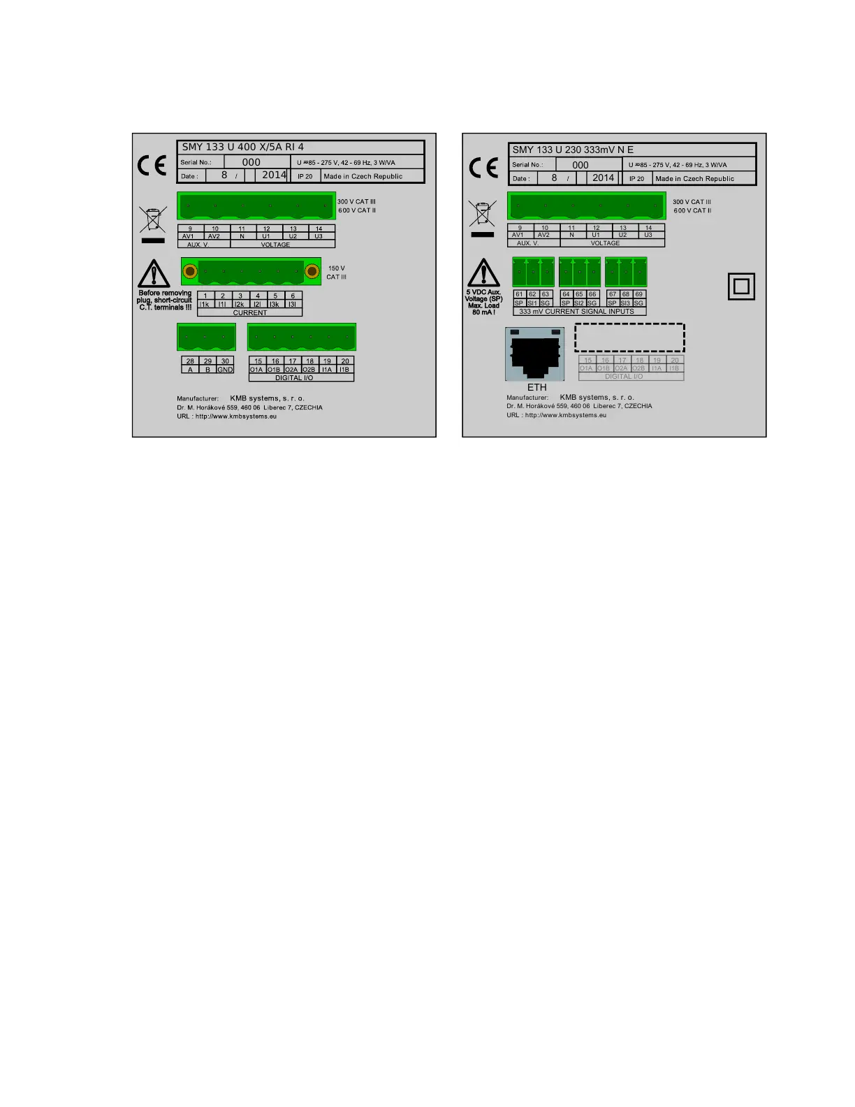
SMY 133 U 400 X/5A RI 4
000
8 2014
(a) terminals for RS485 serial line communication (option 4)
and a digital input with two relay or solid state outputs (op-
tions RR, RI or II).
Manufacturer:
Dr. M. Horákové 559, 460 06 Liberec 7, CZECHIA
URL : http://www.kmbsystems.eu
KMB systems, s. r. o.
13
14
11 129 10
U2
U3
N U1
AUX. V. VOLTAGE
AV1 AV2
O1B O2A
O2B
I1A
I1B
O1A
DIGITAL I/O
15 16 17 18 19 20
333 mV CURRENT SIGNAL INPUTS
SI1SP SG
61 62 63
SI2SP SG
64 65 66
SI3SP SG
67 68 69
ETH
SMY 133 U 230 333mV N E
000
8 2014
(b) option for current CTs or flexible probes with X/333 mV
output, RJ-45 connector for Ethernet (option E), without in-
puts and outputs (option N in I/O).
Obr´azek 3: Back side of the SMY 133 with terminals for serial line, I/O and Ethernet options.
2.2.1 Supply voltage
The supply voltage (according to the technical specifications and the instrument type) connects to terminals
AV1 (no. 9) and AV2 (no. 10) via a disconnecting device (switch – see the wiring diagram fig. 16b, fig. 16c). It
must be located at the instrument’s proximity and easily accessible by the operator. The disconnecting device
must be marked as such. A circuit breaker for nominal current of 1 Amp of the required rating makes a suitable
disconnecting device. Its function and working positions must be clearly marked (symbols ’O’ and ’I’ according
to IEC EN 61010-1).
2.2.2 Measured voltage
The measured phase voltages are connected to terminals U1 (no. 12), U2 (no. 13), U3 (no. 14). The common
terminal to connect the neutral wire is identified as N (no. 11; it remains unused with delta and Aron connections).
It is suitable to protect the voltage lines measured for example with 1A fuses of the required rating. Measured
voltages can also be connected via instrument voltage transformers. A connection cable maximum cross section
area is 2.5 mm
2
.
2.2.3 Measured currents
The instruments are designed for indirect current measurement via external CT only. Proper current signal
polarity (k, l terminals) must be observed. You can check the polarity by the sign of phase active powers on the
instrument display (in case of energy transfer direction is known, of course). Terminals I2k, I2l are not used in
case of the Aron connection.
6
 Loading...