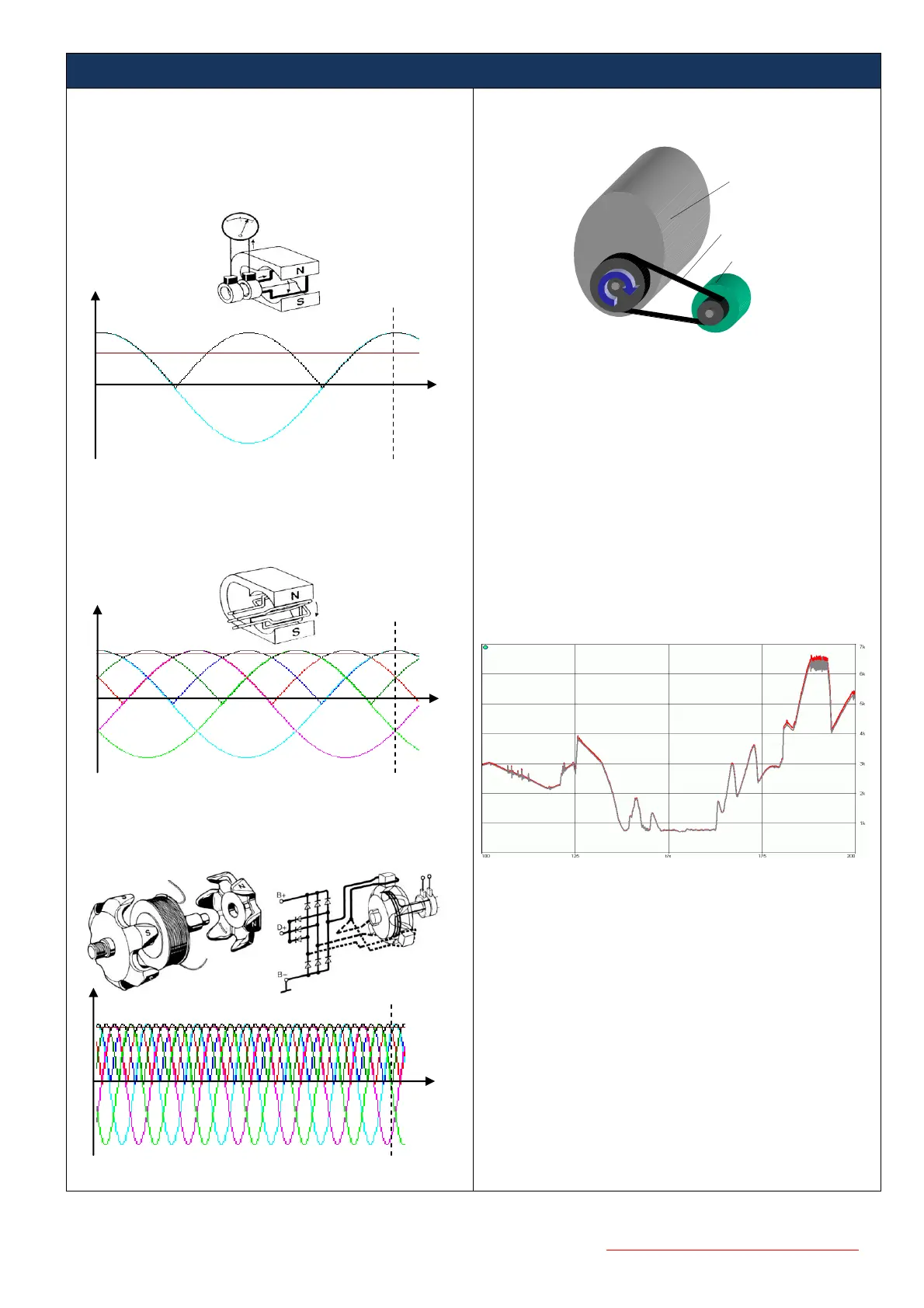
Considering the simplest physical generator with a rotating
wire winding inside a magnetic field produced by two magnetic
poles (one pole pair = north and south) - the output voltage is a
sine wave (blue line) with one cycle per revolution. After
rectification with diodes we get an alternating DC voltage with
2 pulses per revolution (black line) and a resulting average
voltage (brown line).
To imagine a three-phase generator we add two independent
wire windings. Now we have 3 sine wave voltages which are
spaced about 120° out of phase. After three-way rectification
with six diodes the result is an alternating DC voltage with 6
pulses per revolution (black line) and an increased average
voltage against the generator with one winding.
In practice generators for automobiles have more than two
poles. In most cases here we find 12 poles (6 pole pairs) and
sometimes also 16 poles (8 pole pairs). For the first one we get
from every phase 6 cycles per revolution and after rectification
an alternating DC voltage with 36 pulses.
By connecting to an automotive cigarette lighter socket the
measurement unit RPM-8000 PRO senses the small AC ripple
of the vehicle board net DC supply voltage and generates on
its outputs both a TTL digital pulse train and an analog voltage
signal. These signals are “per design” linear to the alternator
RPM and by the linear drive belt relationship also to the engine
RPM. The scaling factor can determined by the relation
between the effective diameters of the engine and the
alternator pulleys.
Accuracy:
Next diagram shows a part of a test measurement of a famous
German automobile manufacturer. The RPM reference signal
was obtained from the car internal CAN bus, which will also
used for the electronically engine management. To verify the
dynamical performance, the RPM signal was provide with an
additional scaling factor of 1.02 - actually both curves are
congruent.
In practice the generated alternator ripple also includes
electrical noise and disturbances from other electrical devices
and loads connected to the vehicle supply. In petrol engine
vehicles this is mainly due to the ignition system and is
relatively straight-forward to eliminate. In Diesel engine
vehicles however the main noise source is from the electronic
injection system and, due to the spectral content of the
injection signals, is very difficult to decouple from the relatively
small signal of interest from the alternator. This technical
background helps to explain the different accuracies of the
RPM signal, which are achieved: approx. 0.5% for Petrol and
approx. 1.5% for Diesel engines. To improve the signal-to-
noise ratio, additional resistive loads such as rear window
heater and lights (not gas discharge lamps) should be
turned on. All inductive loads such as air conditioning
system, air blower, light dimmer, sliding roof and door
opener should remain off! This process increases the
accuracy of the output signal in every case
 Loading...