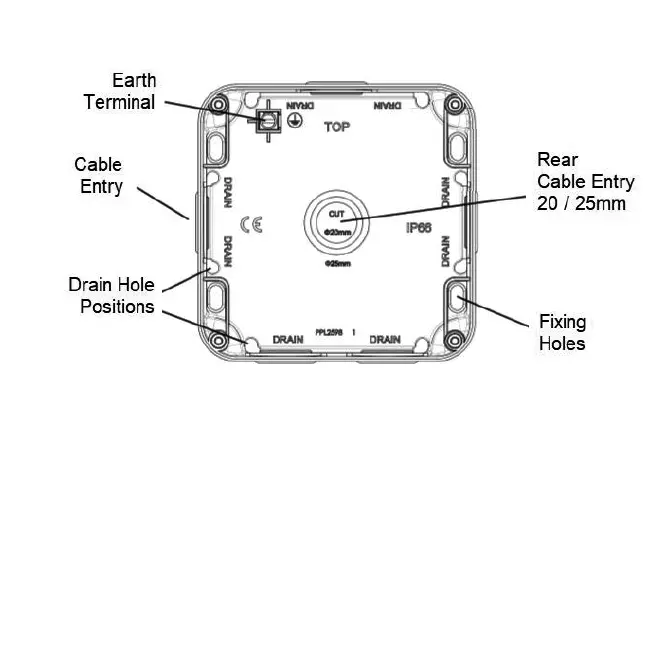
Fig. 2
• Remove one or more of the pre-fitted blank plugs as required by pushing out from the inside and install
a suitable IP rated gland or adaptor (not supplied). For rear entry, cut or drill a 20 / 25mm hole where
marked and install a suitable IP rated grommet (not supplied). Unused cable entries must have the
blank plugs fitted
• Feed the mains cables into the unit and secure the baseplate to the surface. The fixing holes are
slotted to allow some rotational adjustment
• Replace the gasket onto the backbox, then wire as shown in Fig. 3 ensuring that correct polarity is
observed: L - Live (brown), E - Earth (green/yellow), N - Neutral (blue)
Fig. 3 OP6N OP63N
• An earth connection must be made to the earth terminal of the accessory. Use green/yellow sleeving
on earth conductors that are not insulated. The earth terminal in the backbox is provided for
convenience and does not need to be connected
• Check all electrical connections are secure with no loose strands of cable
• Ensuring the gasket does not become damaged or pinched, fit the fused spur assembly onto the
backbox taking care not to compress, damage, or trap any cables, and secure with the screws
provided - do not overtighten
• Fit screw covers
• Replace the 13A fuse with one of a lower rating (not supplied) if required
• Switch on and check for correct operation
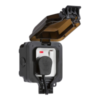
For security, and to prevent unwanted tampering with the product, a lug feature with a 6mm hole is provided to
accept a padlock or similar locking security device (see Fig. 4)
Fig. 2
 Loading...