INSTALLATION
Please note: the unit should be fixed to a rigid flat surface as unevenness could cause
damage to the product or affect operation
• Provide power to the required point of installation (refer to BS7671 for correct cabling
methods)
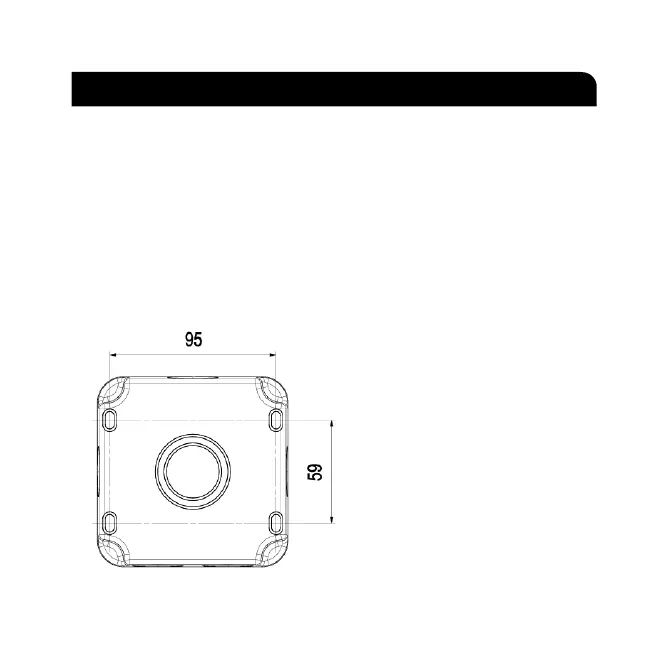
• Remove the front assembly from the backbox and carefully lift off the gasket. Drill the
required number of fixing holes in the backbox (see Fig. 1)
• Using the backbox as a template, mark the location for, and drill the fixing holes ensuring
not to infringe with any gas/water pipes or electrical cables. The backbox can be rotated
through 180°, if required, to position the two cable entries on the top
• The backbox has drain hole drilling guides
marked (see Fig. 2). Drilling a drain hole
is advised if the unit is installed in a
location subject to temperature
fluctuations where build-up of
condensation may occur. It is not advised
if the unit will be subject to spray or
jets as drilling a drain hole will reduce the
IP rating. A 3-5mm hole can be drilled
at the bottom back edge of the enclosure
where marked. If wiring in conduit to the
bottom entry, then the drain hole should
be drilled at the lowest point of the
conduit run not in the backbox
Fig. 1
INSTALLATION & MAINTENANCE MANUAL
ICONS: 230V, Class I, IP66
These instructions should be read carefully and retained after installation by the end user for future reference
and maintenance.
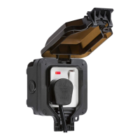
These instructions should be used to aid installation of the following products:
OP6N / OP63N
SAFETY
• This product must be installed in accordance with the latest edition of the IEE Wiring Regulations
(BS7671) and current Building Regulations. If in any doubt, consult a qualified electrician
• Please isolate mains prior to installation or maintenance
• Check the total load on the circuit (including when this product is fitted) does not exceed the rating of
the circuit cable, fuse or circuit breaker
• Please note the IP (Ingress Protection) rating of this product when deciding the location for installation
• Do not overload this accessory or subject it to conditions outside its rating
• This product is Class I and must be earthed
• This product is IP66 rated
INSTALLATION
Please note: the unit should be fixed to a rigid flat surface as unevenness could cause damage to the product or
affect operation
• Provide power to the required point of installation (refer to BS7671 for correct cabling methods)
• Remove the front assembly from the backbox and carefully lift off the gasket. Drill the required number
of fixing holes in the backbox (see Fig. 1)
• Using the backbox as a template, mark the location for, and drill the fixing holes ensuring not to
infringe with any gas/water pipes or electrical cables. The backbox can be rotated through 180
0,
if
required, to position the two cable entries on the top
Fig. 1
• The backbox has drain hole drilling guides marked (see Fig. 2). Drilling a drain hole is advised if the
unit is installed in a location subject to temperature fluctuations where build-up of condensation may
occur. It is not advised if the unit will be subject to high pressure jets as drilling a drain hole will reduce
the IP rating. A 3-5mm hole should be drilled at the bottom back edge of the enclosure where marked.
If wiring in conduit to the bottom entry, then the drain hole should be drilled at the lowest point of the
conduit run not in the backbox
 Loading...