When installing or moving the compressor
This compressor is extremely top heavy. The
compressor must be bolted to the floor with
vibration pads before operating to prevent
equipment damage, injury or death. Do Not
tighten bolts completely as this may
cause stress to the tank welds.
To reduce the risk of a dangerous
environment
1. Keep work area well lit.
2. Operate compressor in a well-ventilated
area free from flammable liquids and vapors.
3. Operate compressor in a ventilated area so
that compressor may be properly cooled and
the surrounding air temperature will not be
more than 100°F.
4. Never use a compressor in a wet
environment.
5. Protect material lines and air lines from
damage or puncture. Keep hose and
wires away from sharp objects, chemical
spills, oil, solvents and wet floors.
Do Not secure compressor with toggle bolts
into drywall. Drywall sheeting or plaster will not
support the weight of the compressor.
WARNING
Page 2
6. A minimum clearance of 18 inches between
the compressor and a wall is required
because objects could obstruct airflow.
7. The compressor should be located where it can
be directly wired to a circuit breaker. The
compressor should be wired by a qualified
electrician.
8. Never store flammable liquids or gases in
the vicinity of an operating compressor.
9. Do Not locate the compressor air inlet near
steam, paint spray, sandblasting areas or
any other source of contamination. The
debris could damage the motor and pump.
Never use plastic (PVC) pipe for compressed
air. Serious injury or death could result.
Never use the shipping skid for mounting the
compressor.
This compressor is not intended for outdoor
installation.
Never install a shut off valve between the compres-
sor pump and tank. Personal injury and/or
equipment damage could occur.
WARNING
CAUTION
NOTICE
WARNING
WARNING
Before each use
1. Keep work area clean. Cluttered areas and
benches invite accidents.
2. The floor must not be slippery from wax or
dust.
1. To reduce the risk of injury from accidental
starting, turn the switch off and disconnect
power.
2. If any part is missing, bent or broken in any
way, or any electrical part does not work
properly, keep the compressor off and dis-
connect power. Do Not use if defect is found.
3. Check hoses for weak or worn condition
before each use, making certain all connect-
ions are secure. Do Not use if a defect is
found.
Inspect your work area Inspect your compressor
ILLUSTRATION PART PART
NUMBER NUMBER DESCRIPTION
01 3660100 Crankcase
02 3630000 Cylinder
03 3860400 Head (NS18S)
3860401 Head (B3800)
04 3660200 Crankshaft
05 3660160 Crankcase Bottom
06 2840050 Valve Assembly
07 1421100 Piston
08 3610100 Conrod
09 9140040 Circlip
10 9020011 Step Ring
11 9020041 Compression Ring
12 9020071 Oil Ring
13 FS008 Filter Assembly (NS18S)
13a 2281000 Filter Assembly (B3800)
16 2060690 Main Bearing Housing (NDS)
17 2060590 Main Bearing Housing (DS)
18 9170030 Main Bearing (6205)
19 9024021 Oil Fill Plug
20 9163010 Oil Seal
21 9110014 Flywheel Bolt
22 9004008 Flywheel Washer
23 3650100 Crankcase Bottom Gasket
24 3650201 Frame Gasket
25 2850300 Cylinder Gasket
26 2850400 Head Gasket
27 2050500 Bearing Housing Gasket
28 3670200 Aftercooler Gasket
29 9101594 Head Bolt
31 9101144 Aftercooler Bolt
32 9101094 Bearing Housing Bolt
33 9107254 Cylinder Bolt
34 9114273 Crankcase Bottom Bolt
Oil Drain Plug35 9101154
36 9022001 Oil Sight Glass
37 3600100 Flywheel
38 3021200 Wrist Pin
39 3670102 Aftercooler
40 FE004 Filter Element (NS18S)
40a 4981100 Filter Element (B3800)
41 FSAD01 Filter Adapter
Gasket Kit 3650055
Page 11
B3800 and NS18S Single Stage Compressor Pumps
Oil Drain Tube35a 9053853
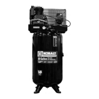
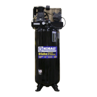
Note: Tank Outlet Size: 1/2” NPT for Models K7045V and K7060HFV
3/4” NPT for Model K7580V2
 Loading...